Fillet weld size directly affects joint strength, load capacity, and fabrication quality, but choosing the correct dimensions requires more than estimating the weld by eye. A Fillet Weld Size Calculator and Formula helps determine the required weld size from its leg length, throat thickness, and design requirements.
For an equal-leg fillet weld, the effective throat is approximately 0.707 times the leg size, making this relationship essential for accurate calculations.
An undersized weld may fail to carry the intended load, while an unnecessarily large weld increases filler metal consumption, heat input, distortion, and welding costs.
Whether you’re fabricating steel frames, joining structural plates, or checking weld dimensions during inspection, understanding the formula helps you make reliable decisions.
Knowing how to calculate leg size and effective throat thickness will help you select appropriate weld dimensions and evaluate whether a fillet weld meets the intended design requirements.
Fillet Weld Size Calculator
Core Formulas That Convert Leg Size into Load Capacity
The geometry of a fillet weld controls every strength calculation. Designers and welders work with two primary dimensions: the leg length specified on the drawing and the theoretical throat that actually carries shear.
Theoretical Throat for Equal-Leg Fillets
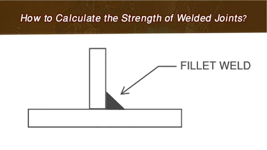
For two plates meeting at 90° and joined by an equal-leg fillet of leg size , the theoretical throat is the shortest distance from the root to the face:
This factor is simply or . A ¼-inch (0.250 in) leg therefore yields a throat of 0.177 in; a ⅜-inch leg yields 0.265 in. The effective weld area is then , where is the effective length of the weld.
Nominal Strength per AISC 360
AISC Section J2.4 treats the weld metal as failing in shear on the throat plane. Nominal strength is:
where is the electrode classification strength (70 ksi for E70XX electrodes). LRFD design strength multiplies by the resistance factor ; ASD divides by the safety factor . Substituting the throat expression for longitudinal loading gives the convenient per-inch values shown below for E70XX.
| Leg Size | Throat t (in) | LRFD ϕ (kip/in) | ASD (kip/in) |
|---|---|---|---|
| 1/8 in (0.125) | 0.088 | 2.78 | 1.86 |
| 3/16 in (0.188) | 0.133 | 4.18 | 2.78 |
| 1/4 in (0.250) | 0.177 | 5.57 | 3.71 |
| 5/16 in (0.313) | 0.221 | 6.96 | 4.64 |
| 3/8 in (0.375) | 0.265 | 8.35 | 5.57 |
| 1/2 in (0.500) | 0.354 | 11.14 | 7.42 |
These figures assume pure longitudinal shear. Transverse loading receives a directional strength increase of , raising capacity by up to 50 % when the load is perpendicular to the weld axis.
Minimum and Maximum Fillet Sizes Required by Code
Code minimums exist to guarantee adequate heat input and fusion; maximums prevent undercutting the edge of thinner material.
Minimum Size Based on Material Thickness
AISC Table J2.4 (and the corresponding AWS D1.1 table) sets the smallest leg that may be detailed. Current editions reference the thinner part joined:
| Thickness of Thinner Part | Minimum Fillet Leg |
|---|---|
| ≤ ¼ in (6 mm) | ⅛ in (3 mm) |
| > ¼ in to ½ in (6–13 mm) | 3/16 in (5 mm) |
| > ½ in to ¾ in (13–19 mm) | ¼ in (6 mm) |
| > ¾ in (19 mm) | 5/16 in (8 mm) |
The weld size need not exceed the thickness of the thinner part. When the thicker part governs in older references, the same numerical values appear; always confirm the edition used on the project.
Maximum Size Along Exposed Edges
Along the edge of material thinner than ¼ in the maximum fillet equals the material thickness. For material ¼ in and thicker the maximum detailed size is the material thickness minus 1/16 in, unless the drawing explicitly requires a built-out weld that restores full throat. Exceeding this limit creates a notch that reduces fatigue life and can cause undercut that is difficult to repair.
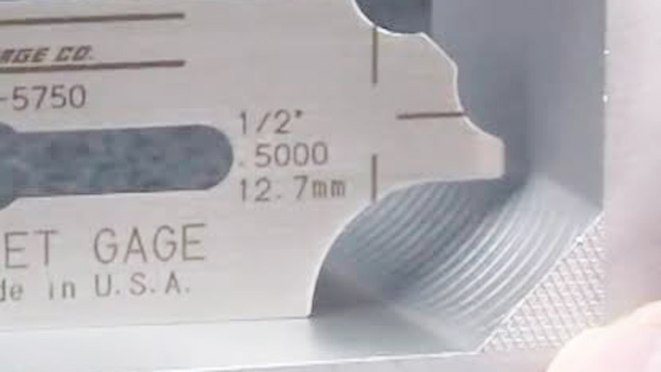
Image by tktk@penntoolco
Calculating the Required Leg Size for a Known Load
Once the applied force, weld length, and electrode strength are known, the required leg follows directly from rearranging the strength equation.
Longitudinal Shear Case
Solve for leg size:
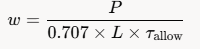
where is the design force (factored for LRFD or service for ASD) and τallow is the design shear stress on the throat (0.45 for LRFD or 0.30 for ASD). For two parallel welds sharing the load, use the total length of both welds.
Round the result up to the next standard increment (1/16 in or 1 mm) and then verify that the chosen size also satisfies the code minimum for the plate thickness.
Transverse and Combined Loading
When the load is not parallel to the weld axis, insert the directional factor into the capacity equation before solving for ( w ). For eccentric connections the elastic vector method or instantaneous center of rotation method is required; simple length × throat calculations understate the peak stress at the ends of the weld group.
In those cases the “calculator” becomes a spreadsheet that resolves each weld segment into force components, finds the resultant on the throat, and iterates leg size until the highest resultant stays below the allowable.
Handling Unequal-Leg and Skewed Fillets
Equal-leg 90° geometry is the default assumption. Real joints frequently deviate.
Unequal Legs
When the two legs differ, the theoretical throat is the altitude to the hypotenuse of the actual triangle formed by the two legs:
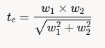
A conservative shop practice is to use 0.707 times the smaller leg; the exact formula yields a larger throat and may allow a smaller deposit if the drawing permits unequal legs.
Joint Angles Other Than 90°
For dihedral angles between 60° and 135° the effective throat factor changes. AWS D1.1 supplies tabulated multipliers that replace the constant 0.707. Angles outside this range are treated as partial-joint-penetration groove welds rather than fillets, and the throat is measured differently.
Practical Decision Sequence for Shop and Field
- Identify the governing code (AISC 360, AWS D1.1, or project specification) and the electrode strength.
- Determine the applied force and the available weld length(s).
- Compute the required theoretical throat from force, length, and allowable stress.
- Convert throat to leg size with the 0.707 factor (or the exact unequal-leg formula).
- Round up to a standard size and check against the code minimum for the thinner plate and the maximum for any exposed edge.
- Confirm that the chosen size can be deposited in the available position without excessive passes or distortion.
This sequence produces a size that satisfies both strength and fabrication constraints. When the calculated size falls below the code minimum, the minimum governs; when it exceeds practical single-pass limits (typically 5/16 in or 8 mm for most processes), multiple passes or a change to a groove weld becomes necessary.
Selecting the correct fillet size is therefore a balance of three numbers: the force that must be transferred, the length of weld that can be placed, and the electrode strength available. Once those three are fixed, the 0.707 throat relationship and the tabulated code limits fix the leg dimension.
Advanced practice further reduces cost by placing transverse segments where possible to capture the directional strength increase and by verifying that the base-metal shear capacity at the fusion face does not govern before the weld metal itself.
Wrapping Up
How do you calculate fillet weld size from load?
Divide the design force by (0.707 × total weld length × design shear stress on the throat). Round the resulting leg size up to the next standard increment and check code minimums.
What is the formula for fillet weld throat?
For an equal-leg 90° fillet, theoretical throat = 0.707 × leg size. For unequal legs the throat equals (leg1 × leg2) / √(leg1² + leg2²).
What is the minimum fillet weld size for ½-inch plate?
Per AISC Table J2.4 the minimum is 3/16 in when the thinner part is over ¼ in through ½ in.
How much stronger is a transverse fillet than a longitudinal one?
AISC allows a directional strength increase of up to 50 % when the load is perpendicular to the weld axis, expressed by the factor (1 + 0.50 sin¹·⁵ θ).