Building a portable welding table requires balancing strength, stability, and mobility without making the structure too heavy to move around the shop or job site. Knowing how to build a portable welding table helps you create a practical work surface that supports metal fabrication, holds workpieces securely, and withstands the heat and demands of everyday welding.
Poor material selection, weak leg bracing, or an undersized tabletop can cause flexing, alignment problems, and unsafe working conditions, especially when handling heavier steel components. A well-designed table should provide a flat, durable surface, sufficient load capacity, and a stable base while remaining easy to transport and store.
By choosing suitable steel dimensions, planning the frame, and using proper welding techniques, you can build a portable welding table that fits your workspace, budget, and fabrication needs.
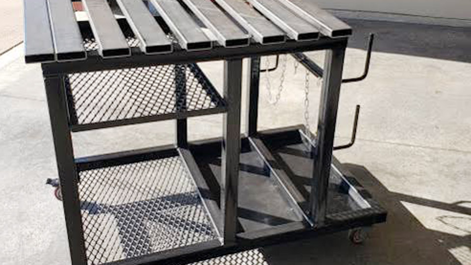
Image by r/Welding
Choosing Size and Height for Real Shop Constraints
Table footprint and working height control both usability and true portability more than any other single decision.
Footprint Limits Imposed by Doors and Aisles
Most garage and small-shop doorways measure 30–36 inches wide. A finished table wider than 30–32 inches becomes awkward to roll through openings once casters and any lower shelf are added. Practical portable sizes fall in the 24 × 36 inch to 36 × 48 inch range.
A 30 × 48 inch top balances clamp room for typical gate or bracket work against the ability to navigate around parked vehicles or tool cabinets. Larger surfaces gain project capacity but rapidly increase plate weight and reduce the chance the table will actually be moved regularly.
Working Height Calculated from Elbow Position
Target finished height sits near standing elbow height for the primary user—typically 34–36 inches from floor to top surface for welders between 5 ft 6 in and 6 ft 0 in. Measure by standing upright with elbows bent 90 degrees; the table surface should land slightly below that line so the weld pool remains visible without excessive stooping.
Subtract top-plate thickness, frame-rail height, and caster height from the target to determine exact leg length. Seated work or very tall users may drop or raise this by 2–3 inches, but fixed-height designs rarely justify adjustable legs on a portable unit because complexity and weight rise quickly.
Overhang Required for Clamp Access
Leave 2–3 inches of plate overhang beyond the frame on at least the long sides and preferably all four edges. This clearance lets C-clamps and locking pliers bite the work without striking the tubing. Zero-overhang designs force every clamp to fight the frame and limit fixturing options on longer members.
Selecting Top Plate Thickness and Frame Tubing
Material cross-section dictates stiffness, heat-sink capacity, and total mass that must be moved.
Plate Thickness Versus Weight and Flatness
Hot-rolled A36 plate is the standard choice. Approximate weights are 10.2 lb per square foot for ¼ inch, 15.3 lb for ⅜ inch, and 20.4 lb for ½ inch. A 30 × 48 inch (10 sq ft) top therefore weighs roughly 102 lb at ¼ inch, 153 lb at ⅜ inch, and 204 lb at ½ inch before the frame is added.
For portable tables that must roll frequently, ¼ inch keeps mass manageable while still resisting moderate thermal distortion when properly supported. ⅜ inch is the better everyday compromise for most shops: it remains flat under typical MIG and stick heat input and tolerates hammering or clamping without permanent oil-canning.
Reserve ½ inch for fixed heavy-fabrication tables; the extra mass defeats portability unless high-capacity casters and a second person are always available. Verify plate flatness with a straightedge before purchase—warped plate cannot be corrected after welding.
Square-Tube Size and Wall Thickness for the Frame
2 × 2 inch square tube with 11-gauge (approximately ⅛ inch / 0.120 inch) wall or heavier forms the backbone of most successful portable builds. Thinner walls flex under offset loads; 3/16 inch or ¼ inch wall adds rigidity with modest weight penalty. Avoid galvanized tube—the zinc coating produces hazardous fumes when welded.
Cut all members square with a cold saw or band saw; chop-saw cuts require careful deburring to maintain fit-up. Perimeter rails carry the top; internal cross members spaced no more than 16–18 inches apart support the plate against deflection. Legs use the same tubing, cut to identical length so the finished surface remains level.
Lower Shelf and Bracing Material Choices
An optional lower shelf of expanded metal or 14-gauge sheet adds storage for the welder and consumables while increasing torsional stiffness. Expanded metal lets slag and grinding dust fall through. Diagonal or horizontal bracing between legs, made from the same tube or from angle iron, prevents racking when the table is pushed or when a heavy workpiece is clamped off-center.
Mobility Options: Casters Versus Folding Legs Versus Fixed Feet
True portability requires a conscious trade-off between rolling ease, storage volume, and stability under load.
Locking Swivel Casters for Daily Movement
Four locking swivel casters rated well above the combined weight of table plus heaviest expected workpiece are the most common solution. A ⅜-inch top on a 30 × 48 inch frame plus legs and shelf easily exceeds 250–300 lb; choose casters rated 500–1,000 lb each so the load stays within a safe margin. Mount them on plates welded to the bottom of the legs.
Two fixed and two swivel casters improve tracking in long shops, but four swivel units give maximum maneuverability in tight spaces. Always lock the brakes before welding; unlocked casters allow the table to creep under torch or gun force.
Folding or Collapsible Leg Designs
Folding legs reduce storage height to roughly 8–12 inches and allow the table to ride in a truck bed or lean against a wall. Commercial examples use spring-loaded pins or double-locking mechanisms and claim 350–1,000 lb capacity. DIY versions require careful hinge design and stop plates so the legs cannot collapse under load.
Folding adds complexity and potential play; the finished surface must still remain rigid when deployed. Height adjustment ranges of 26–37 inches appear on some portable commercial units, but fixed-height DIY tables with good casters usually prove simpler and stronger.
Leveling Feet for Semi-Permanent Placement
If the table will spend most of its life in one location yet still needs occasional relocation, heavy-duty leveling feet or a combination of two casters and two feet can work. Leveling feet eliminate the slight compliance of caster wheels and improve stability for precision layout, but they eliminate true one-person mobility.
Frame Design Details That Prevent Racking and Distortion
Geometry and joint design determine whether the table remains square after months of use.
Cross-Member Spacing and Load Paths
Internal cross members under the top must transfer load from the plate into the perimeter rails without allowing the surface to oil-can. Spacing of 12–16 inches works for ¼-inch plate; ⅜-inch plate tolerates slightly wider spans.
Place the outermost cross members close to the ends so clamp loads near the edge do not bend the plate downward. Continuous perimeter rails with mitered or butted corners form a closed box that resists twisting far better than open angle-iron frames.
Gussets and Diagonal Bracing Locations
Weld triangular gussets or short diagonal braces at the top of each leg where it meets the frame. These members stop the legs from folding inward or outward under lateral force. Lower horizontal stretchers between legs further stiffen the base.
On longer tables, a single diagonal brace on each long side or an X-brace pattern on the ends eliminates racking when the table is pushed diagonally across the floor.
Ground-Path and Electrical Considerations
Weld a dedicated ground-clamp pad—a short length of ¼-inch plate or a large bolt head—onto one leg or the underside of a rail. This provides a clean, reliable electrical path without relying on paint or mill scale. Keep the pad accessible and free of heavy slag buildup.
Assembly Sequence That Keeps the Top Flat
Weld sequence and fixturing control the single most common failure mode: a twisted or crowned top.
Cutting and Dry Fit Before Any Welding
Cut every tube to exact length and deburr thoroughly. Lay the perimeter and cross members on a known-flat surface (concrete floor checked with a level or a large surface plate). Clamp and dry-fit the entire top frame, checking diagonals for equal measurement. Only after the frame sits square and flat should any tack welds be placed.
Tack-Weld Strategy and Distortion Control
Tack opposite corners first, then the remaining joints, using short tacks. Check diagonals and flatness after every few tacks. Full-penetration welds on one side only will pull the frame; balance heat by welding short segments on alternating sides and allowing cooling time.
Stitch welding the top plate to the frame—intermittent welds rather than continuous seams—further reduces residual stress and keeps the plate flatter. Clamp the plate firmly to the frame before welding so it cannot lift or warp.
Final Inspection and Correction Methods
After all welding, place a straightedge across the top in multiple directions. Minor high spots can be ground carefully; low spots are harder to correct and usually indicate inadequate cross-member support or uneven tacking.
Verify that all four casters contact the floor simultaneously when the table is unloaded; shimming one caster mount may be required if leg lengths vary by more than 1/16 inch.
Adding Clamping Features and Practical Details
A portable table gains value when it accepts common fixtures without extra setup time.
Edge Overhang and Slot Options
The 2–3 inch overhang already noted provides the primary clamping surface. Some builders mill or plasma-cut intermittent slots parallel to the long edges for additional clamp clearance or for inserting stop blocks.
Full-grid fixture holes (⅝ inch or 16 mm on 2-inch centers) turn the table into a modular fixture system but add significant drilling or machining time and cost; they are optional on a basic portable unit.
Tool Storage and Accessory Mounts
A lower expanded-metal shelf keeps the welder, wire, and helmet off the floor. Side-mounted hooks or short vertical tubes hold clamps and squares within reach. A simple vertical plate or pegboard panel attached to one end organizes frequently used tools without cluttering the work surface.
Surface Finish and Corrosion Control
Leave the top bare steel or apply a light coating of weldable primer only on the frame and legs. Heavy paint on the working surface interferes with grounding and collects slag. A light oil wipe after use slows rust on the plate without affecting weld quality.
Weight, Capacity, and Transport Reality Checks
Final mass and load rating decide whether the table remains portable in practice.
Calculating Total Weight Before Casters Are Chosen
Add plate weight, frame tubing weight (approximately 2–3 lb per linear foot for 2 × 2 × ⅛ inch tube), bracing, shelf, and casters. A realistic 30 × 48 inch table with ⅜-inch top often lands between 250 and 400 lb.
Confirm that chosen casters carry at least 1.5 times that figure under dynamic loading. Test-roll the completed table with a representative workpiece before declaring the design successful.
Load Capacity Versus Point Loading
Distributed capacity of 500–1,000 lb is common on well-built portable tables. Point loads from a heavy vise or concentrated clamp force can exceed local capacity even when the overall rating is adequate. Cross members and thicker plate improve resistance to point loading.
One-Person Movement and Storage Envelope
If the table cannot be rolled by one person across a typical shop floor or cannot fit through the shop door with a moderate load, the design has failed its portability requirement. Measure the collapsed or rolling envelope against actual door and aisle clearances before final welding.
A well-executed portable welding table places a flat, clamp-ready surface exactly where the work is and then moves out of the way when floor space is needed for other tasks.
The decisive technical choices—plate thickness matched to expected heat and mass, 2 × 2 inch tubing with adequate wall, correct caster rating, and a weld sequence that preserves flatness—determine whether the table becomes a daily asset or an immovable obstacle.
Advanced builders further refine heat input by using stitch welds and balanced sequences so residual stress never accumulates enough to crown the surface under repeated thermal cycles.