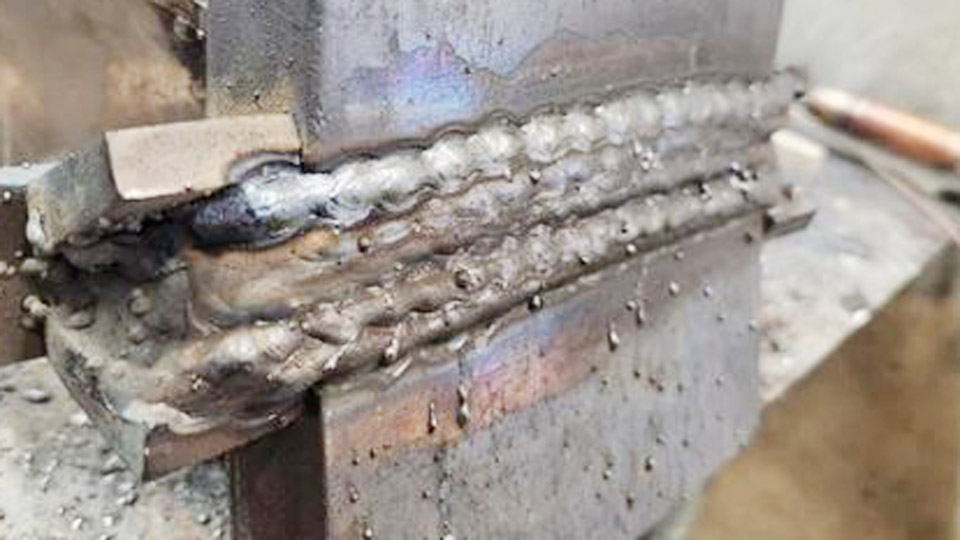
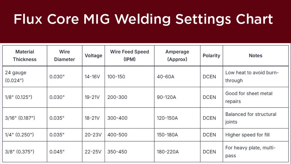
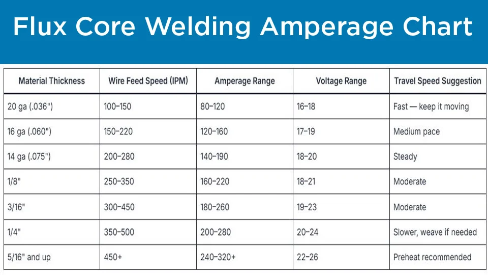
Wrong polarity or mismatched voltage and wire feed speed on self-shielded flux-cored wire produces a wild, popping arc, heavy spatter, and porosity that fails under load.
A practical gasless flux core welding settings chart solves that by linking wire diameter, material thickness, voltage, and wire feed speed (IPM) to the correct DCEN polarity and contact-tip-to-work distance.
These parameters control heat input, slag coverage, and penetration depth on outdoor or windy jobs where shielding gas is impractical.
Using published operating windows for common E71T-11 and E71T-GS wires keeps the arc stable, the slag easy to remove, and the weld metal free of the defects that appear when settings drift outside the recommended band.
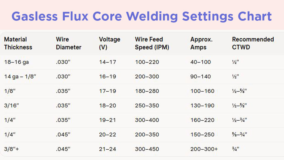
Core Voltage and Wire Feed Speed Ranges by Wire Diameter
Self-shielded wires generate their own shielding gas from the flux core, so the arc behaves differently from solid-wire MIG. Voltage sets arc length and bead width; wire feed speed sets amperage and deposition rate. Both must stay inside the manufacturer window for the chosen diameter.
.030-Inch Wire Operating Window
On 110 V or compact 140–180 A machines, .030-inch E71T-11/GS wire covers 18-gauge through roughly 3/16-inch plate. Typical flat-position ranges run 14–19 V at 100–350 IPM, producing approximately 40–150 A. Thinner sheet (18–16 ga) stays at the low end (14–16 V, 100–200 IPM) to limit burn-through.
At 1/8 inch the window opens to 16–18 V and 200–300 IPM. Contact-tip-to-work distance (CTWD) of ½ inch keeps resistance low and arc force consistent. Exceeding 19 V on this diameter widens the arc column and increases spatter without adding useful penetration.
.035-Inch Wire Operating Window
The most common hobby and light-fabrication diameter, .035-inch wire handles 1/8-inch to 5/16-inch material on 200 A-class machines. Flat-position settings typically fall between 15–21 V and 150–400 IPM, yielding 80–200 A. For 1/8-inch plate start near 17–19 V and 200–280 IPM. On 3/16-inch material raise to 18–20 V and 250–350 IPM.
At ¼ inch the upper end (19–21 V, 300–400 IPM) supplies the heat needed for full fusion on a single-pass fillet or multi-pass groove. CTWD of ½–⅝ inch is standard; longer stickout drops effective amperage and can produce a colder, convex bead.
.045-Inch and Larger Wire Ranges
Heavier .045-inch and .068-inch wires suit ¼-inch and thicker plate on machines rated 250 A and above. Voltage climbs to 18–24 V while wire feed speed often drops relative to smaller diameters (150–350 IPM for .045 inch) because the larger cross-section carries more current at lower feed rates.
Approximate amperage reaches 150–280 A on .045 inch and higher on larger sizes. These diameters demand a stiffer gun and knurled drive rolls to prevent bird-nesting.
Maximum single-pass thickness is limited by the specific electrode classification—many E71T-11 products are restricted to 5/16 inch or ½ inch unless multi-pass procedures are followed.
Matching Settings to Material Thickness and Joint Type
Thickness determines required heat sink and fusion depth more than any other variable once wire diameter is chosen.
Thin-Gauge Sheet (18 ga to 1/8 Inch)
Keep voltage and wire speed at the lower half of the diameter window. On 16-gauge material with .030-inch wire, 15–17 V and 150–220 IPM prevent burn-through while still melting the edges of a lap or T-joint.
Travel speed stays relatively high (10–15 ipm) so the puddle freezes before the heat builds. Fit-up gaps larger than 1/16 inch require stitch welding or a slight increase in voltage to bridge without undercut.
Medium Plate (3/16 to ¼ Inch)
This range is the sweet spot for .035-inch wire. A 3/16-inch fillet typically runs cleanly at 18–20 V and 250–350 IPM. For a square-butt or single-bevel groove on ¼-inch plate, move toward 19–21 V and 300–380 IPM to obtain root penetration.
Multi-pass work requires thorough slag removal between layers; residual heat from the previous pass effectively raises the working amperage felt by the next bead, so a 5–10 % reduction in wire speed is often necessary on successive layers.
Thicker Sections and Multi-Pass Sequences
Above 5/16 inch, .045-inch wire or multi-pass techniques with .035-inch become necessary. Voltage may reach 21–24 V and wire speed 300–450 IPM depending on machine output. Groove preparation (30–60° included angle) and interpass temperature control become critical.
Preheat is advisable on material thicker than ⅜ inch when ambient temperature is low, because the rapid freeze rate of self-shielded deposits can promote cracking if the base metal remains cold.
Polarity, Stickout, and Machine Setup Decisions
Self-shielded flux-cored electrodes almost always require DCEN (electrode negative). Running DCEP reverses heat balance, produces an unstable arc, and increases spatter dramatically.
Confirm polarity by checking the wire label and reversing the leads inside the machine if it was previously set for solid-wire MIG.
Contact-Tip-to-Work Distance Effects
CTWD (electrical stickout) directly influences resistance heating of the wire and therefore effective amperage. For .030- and .035-inch wires the preferred range is ½–¾ inch. Lengthening stickout beyond 1 inch drops current, softens the arc, and can leave incomplete fusion.
Shortening it below ⅜ inch raises current, increases burn-back risk, and may melt the contact tip. Consistent stickout is more important than exact numerical values; operators who maintain a steady distance produce more uniform beads than those who chase perfect meter readings while varying stickout.
Drive-Roll and Liner Considerations
Knurled or V-knurled drive rolls are required for flux-cored wire. Smooth V-groove rolls designed for solid wire crush the softer tubular electrode and cause feeding problems. Liner diameter must match the wire size; an oversized liner allows the wire to wander and increases friction.
Tension should be set just high enough to feed without slippage—excessive pressure deforms the wire and leads to bird-nesting at the drive rolls.
Position-Specific Adjustments to the Base Chart
Gravity changes puddle behavior, so the flat-position numbers must be modified.
Vertical-Up and Vertical-Down Changes
Vertical-up requires a 10–15 % reduction in both voltage and wire feed speed relative to the flat setting. The lower heat keeps the slag from running ahead of the puddle and allows a slight triangular or side-to-side weave.
Vertical-down is possible with many E71T-11 wires but demands faster travel and tighter control; most structural codes prefer vertical-up for critical joints. Start 1–2 V and 30–50 IPM below the flat mid-range and adjust until the bead freezes with a slight convex profile and no undercut.
Overhead Technique and Heat Control
Overhead favors the lower half of the vertical range or slightly higher stickout to support the molten metal. Wire speed is reduced so the deposition rate does not overwhelm the freeze rate. Short arc length and steady travel prevent dripping.
Many operators drop to .030-inch wire for overhead work on thinner sections because the smaller diameter produces a more controllable puddle at the reduced amperages required.
Diagnosing Setting Errors from Arc Sound and Bead Appearance
The arc itself supplies immediate feedback once the parameters are close.
Signs of Insufficient Voltage or Wire Speed
A cold arc produces a harsh crackle, frequent stubbing, and a ropey, high-crowned bead with poor toe fusion. Slag freezes tightly and is difficult to remove. Increase voltage in 1 V increments or wire speed in 20–30 IPM steps until the arc settles into a steady frying-bacon sound and the slag lifts cleanly after cooling.
Signs of Excessive Voltage or Wire Speed
Too much heat creates a long, soft arc, heavy spatter, undercut at the toes, and a flat or concave bead that may show porosity. The contact tip may glow or burn back.
Reduce voltage first, then wire speed if necessary, while maintaining the same CTWD. Excessive voltage is the more common cause of porosity and undercut on self-shielded wire.
Decision Framework for Final Parameter Selection
Begin with the mid-range values from the chart for the chosen wire diameter and thickness. Run a short test bead on scrap of identical thickness and joint geometry. Evaluate fusion by sectioning or by grinding a face and checking for incomplete penetration.
Adjust voltage and wire speed together—raising one without the other usually produces an unbalanced arc. Once the bead profile, slag release, and arc sound match the target, lock the settings and record ambient temperature, CTWD, and machine model.
This empirical calibration accounts for cable length voltage drop, drive-roll condition, and slight differences between electrode brands that generic charts cannot capture.
Wrapping Up
Choosing the correct point inside the published voltage and wire-feed windows for gasless flux-cored wire is a balance of penetration demand against puddle control and slag behavior.
When the arc produces a consistent frying sound, the slag peels in large pieces, and the toes blend without undercut, the settings are right for that joint.
Advanced operators further refine heat input by combining consistent stickout with deliberate stringer-bead sequencing rather than wide weaves, preserving mechanical properties and reducing the risk of slag inclusions on multi-pass structural work.
FAQs
What voltage and wire speed for gasless flux core on 1/8-inch steel?
With .035-inch E71T-11 wire use 17–19 V and 200–280 IPM on DCEN as a starting point; fine-tune on scrap until the arc stabilizes and slag releases cleanly.
Do I need to change polarity for gasless flux core?
Yes. Nearly all self-shielded E71T-11 and E71T-GS wires require DCEN (electrode negative). Running DCEP produces an unstable arc and excessive spatter.
What is a good starting setting for .030-inch gasless wire on 16-gauge metal?
Begin at 15–17 V and 150–220 IPM with ½-inch stickout. Keep travel speed high to avoid burn-through.
Can the same chart be used for vertical welding?
No. Reduce both voltage and wire feed speed 10–15 % from the flat-position values to control the puddle and prevent slag runoff.