Wrong motor speed on a welding positioner causes irregular travel rates that produce inconsistent bead profiles and incomplete fusion. The same mismatch on an engine-driven welder’s alternator shifts auxiliary power frequency and can damage connected tools.
Knowing how to calculate RPM of electric motor from frequency, poles, voltage, or measured Hertz prevents these failures and lets you match shaft speed to joint requirements, abrasive surface feet per minute, or generator output.
Accurate RPM calculation directly controls heat input timing, deposition consistency, and equipment reliability in the shop or field. The methods below give the exact formulas and decision values welders actually use.
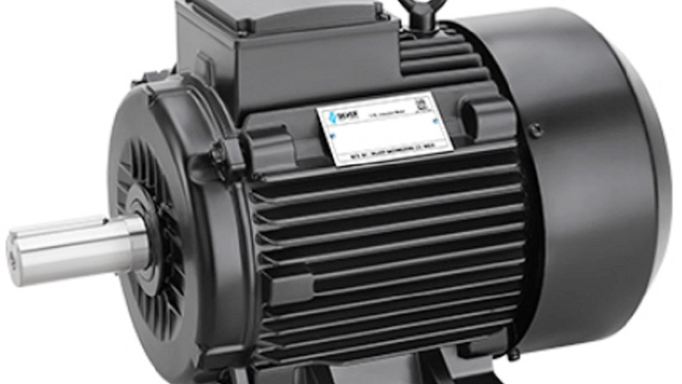
Image by indiamart
Synchronous Speed Formula for AC Induction Motors
Most motors found on welding positioners, cooling fans, compressors, and shop grinders are AC induction types. Their theoretical no-load speed depends only on supply frequency and the number of magnetic poles.
Applying the Core Equation
The synchronous speed in revolutions per minute is given by
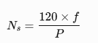
where (f) is the line frequency in hertz and (P) is the total number of poles (always an even integer). The constant 120 converts cycles per second into revolutions per minute while accounting for the positive and negative half-cycles that form one full electrical revolution relative to a pole pair.
A 4-pole motor on 60 Hz power therefore runs at
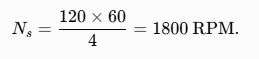
The same motor on 50 Hz yields 1500 RPM. Two-pole designs reach 3600 RPM at 60 Hz; six-pole designs drop to 1200 RPM. These values appear on every standard motor nameplate as the synchronous or “sync” speed.
Standard Pole-Frequency Combinations Used in Welding Shops
| Poles | 60 Hz Synchronous RPM | 50 Hz Synchronous RPM | Typical Welding Use |
|---|---|---|---|
| 2 | 3600 | 3000 | High-speed grinders, some fans |
| 4 | 1800 | 1500 | Positioners, pumps, most shop motors |
| 6 | 1200 | 1000 | Low-speed rotators, heavy positioners |
| 8 | 900 | 750 | Very slow rotation tables |
Selecting a motor with the correct pole count sets the base speed before any gear reduction or VFD is applied. Changing frequency with a variable-frequency drive scales the entire table linearly.
Accounting for Slip to Obtain Actual Running RPM
Induction motors never reach synchronous speed under load. The difference, called slip, produces the torque that turns the shaft.
Calculating Full-Load Speed from Slip Percentage
Actual rotor speed is
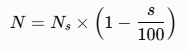
where (s) is slip expressed as a percentage. Typical full-load slip for industrial motors ranges from 2 % to 5 %. A 4-pole, 60 Hz motor with 4 % slip therefore runs at
Nameplates usually list this value as the rated full-load RPM (commonly 1725 or 1750 for 4-pole 60 Hz motors).
Slip increases with torque demand. On a welding positioner carrying a heavy pipe spool the motor may operate at 3–6 % slip; under light load the speed rises closer to synchronous.
Measuring shaft speed with a tachometer or strobe under the actual work load gives the true operating RPM when precision travel speed is required.
Using Nameplate Data to Confirm Slip
Subtract the listed full-load RPM from the calculated synchronous speed, divide by synchronous speed, and multiply by 100 to recover the design slip. If the motor is running noticeably slower than the nameplate full-load figure under normal load, check voltage, phase balance, or mechanical binding before assuming the calculation is wrong.
Calculating RPM for DC Motors
DC motors appear on older wire feeders, some portable grinders, and battery-powered tools. Speed is controlled primarily by armature voltage.
Voltage-Proportional Speed Relationship
When the motor is operated below base speed with constant field strength,
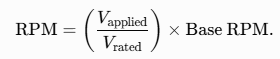
A motor rated 1750 RPM at 90 V will turn at approximately 875 RPM when supplied with 45 V. Permanent-magnet DC motors follow this linear relationship closely; wound-field motors may require field weakening above base speed, which the simple proportion does not cover.
Brushless DC motors used in modern inverter-driven feeders or cordless grinders are often characterized by a Kv rating (RPM per volt). Multiply Kv by applied voltage and apply a load factor (typically 0.85–0.95) for a practical estimate of loaded speed.
Determining RPM When Nameplate Information Is Incomplete
Field conditions frequently present motors with missing or illegible data plates. Two practical methods recover usable speed figures.
Frequency Measurement on Engine-Driven Welders and Generators
Engine-driven welding machines produce auxiliary AC power whose frequency is directly proportional to engine (and alternator) RPM. The same formula used for motors applies:
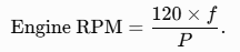
Most Lincoln and Miller units use 2-pole or 4-pole alternators. For a 2-pole machine, RPM ≈ frequency × 60; for a 4-pole machine, RPM ≈ frequency × 30. Measuring 62 Hz on a Ranger-style 2-pole unit indicates roughly 3720 RPM.
Adjusting engine speed until the desired Hertz appears sets the correct high-idle or low-idle RPM without a mechanical tachometer.
Direct Measurement with Tachometer or Strobe
Contact tachometers or optical/strobe units give actual shaft speed under load. Mark the shaft or pulley, illuminate with a calibrated strobe, and adjust until the mark appears stationary; the strobe frequency equals RPM.
This method is essential when verifying positioner travel speed against calculated surface feet per minute or when confirming that a VFD has reached the commanded frequency.
RPM Requirements for Common Welding-Related Equipment
Correct motor speed must be translated into the process parameter that actually affects the weld or the prepared surface.
Positioners and Rotators
Desired surface travel speed in inches per minute is converted to chuck or table RPM by
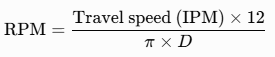
where (D) is the workpiece diameter in inches. A 12-inch-diameter pipe that must travel at 6 IPM requires approximately 1.9 RPM at the chuck. Gear reduction between the motor and the final drive multiplies the required motor RPM by the gear ratio.
Selecting a 6-pole or 8-pole motor (or a VFD set to lower frequency) keeps the motor in its efficient torque band while delivering the slow surface speed needed for TIG or submerged-arc circumferential welds.
Grinders and Abrasive Wheels for Weld Cleaning and Beveling
Abrasive performance is governed by surface feet per minute (SFPM). Wheel RPM is obtained from
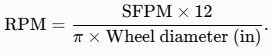
A 7-inch grinding wheel intended for 9000 SFPM must turn at roughly 4900 RPM. Running a high-speed 2-pole motor without proper wheel rating produces unsafe peripheral speeds; underspeeding reduces cutting rate and glazes the abrasive. Always match calculated RPM to the maximum safe operating speed marked on the wheel.
Cooling Fans, Pumps, and Wire-Feed Motors
Fan and pump performance curves are plotted against RPM. Affinity laws show that flow varies linearly with speed while pressure and power vary with the square and cube of speed, respectively.
A cooling fan designed for 1800 RPM that is run at 1500 RPM moves only 83 % of design air volume and may allow overheating of the welder’s power electronics.
Wire-feed motors are usually DC or servo and are calibrated in inches per minute rather than RPM; the internal gear ratio converts motor revolutions into wire speed, so any change in motor voltage or commanded RPM appears directly as a change in deposition rate.
Variable-Frequency Drives and Soft-Start Considerations
A VFD changes the effective frequency supplied to an AC motor and therefore scales synchronous speed in exact proportion. A 4-pole motor commanded at 30 Hz runs at a synchronous speed of 900 RPM.
Torque remains roughly constant up to base frequency provided the VFD maintains constant volts-per-hertz. Above base frequency the drive enters constant-power mode and available torque declines.
For welding positioners this allows continuous speed adjustment without mechanical gear changes; for grinders it permits soft start that reduces inrush current on generator-powered sites.
When a VFD is used, the actual shaft speed still includes slip. The drive’s displayed frequency yields only synchronous speed; a shaft encoder or tachometer feedback is required if closed-loop speed control is necessary for critical circumferential welds.
Decision Framework for Selecting and Verifying Motor Speed
Begin with the required process speed—surface travel rate, SFPM, or generator frequency. Back-calculate the necessary shaft RPM, then apply the gear or pulley ratio to find the motor RPM. Choose a motor whose synchronous or base speed is close to that value so that it operates near its design slip and torque peak.
Confirm actual speed under load with a tachometer or, on engine-driven machines, with a frequency meter. Record the final setting against joint diameter, wheel size, or auxiliary load so the same calculation can be repeated quickly on the next job.
When the calculated RPM falls between two standard motor speeds, prefer the lower-pole-count motor with a VFD rather than an oversized high-pole motor; the drive provides both speed range and soft-start capability that protects generators and reduces mechanical shock on positioner gearing.
Wrapping Up
How do you calculate RPM of a 4-pole motor on 60 Hz?
Synchronous speed is (120 × 60) / 4 = 1800 RPM. Actual full-load speed is typically 1725–1750 RPM after accounting for 2–4 % slip.
What is the formula for motor RPM from frequency and poles?
, where is frequency in Hz and is the number of poles. Multiply by (1 – slip fraction) for loaded speed.
How can I find engine RPM on a welder generator using Hertz?
Measure auxiliary output frequency, then apply RPM = 120 × Hz / number of alternator poles. For common 2-pole units this simplifies to Hz × 60.
Why does actual motor RPM differ from the calculated synchronous speed?
Induction motors require slip to produce torque. Under load the rotor lags the rotating magnetic field by 2–5 %, so shaft speed is always lower than the calculated synchronous value.