A common failure point in mixed-metal plumbing occurs when copper pipe meets a threaded brass valve, faucet, or adapter and the joint weeps or fails under pressure.
The difference in thermal expansion, thread engagement, and surface preparation often produces leaks that show up only after the system is pressurized.
Learning how to connect copper pipe to threaded brass fitting correctly prevents those failures by matching the right transition method—soldered adapter, compression, or direct sweat—to the pressure, accessibility, and permanence required.
Incorrect heat control on brass, missing thread sealant, or poor capillary fill leaves microscopic paths for water. The techniques below deliver measurable, code-compliant joints using real shop values for cleaning, flux, heat, and torque.
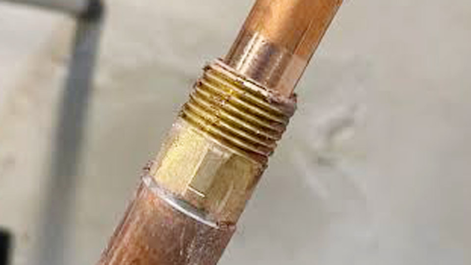
Image by r/askaplumber
Choosing the Right Transition Method for Copper-to-Brass Threads
The joint type determines long-term reliability more than any single tool choice. Each option carries distinct pressure ratings, disassembly potential, and skill demands.
Soldered Adapter with MIP or FIP Threads
A copper or brass sweat-by-male (or female) adapter is the most permanent residential solution. The copper pipe is cleaned, fluxed, and soldered into the socket end; the threaded end then receives PTFE tape or pipe dope and screws into the brass fitting.
Lead-free solder (95/5 tin-antimony or 97/3 tin-copper) melts between 420–464 °F and fills the 0.003–0.006 in capillary gap by surface tension.
Brass requires more torch time than copper because of its lower thermal conductivity; focus the flame on the denser brass body until the flux sizzles and the solder is drawn evenly around the joint.
Compression Fittings for Serviceable Connections
A brass compression fitting accepts the copper tube on one side and provides male or female threads on the other. The ferrule (olive) is compressed against the pipe wall by the nut, creating a mechanical seal without heat.
This method suits locations where future disconnection is likely or open flame is restricted. Torque is critical: overtighten and the ferrule cuts the copper; undertighten and the joint weeps. Two wrenches—one holding the body, one turning the nut—are mandatory to avoid twisting the pipe.
Direct Sweat Brass Fittings When Available
Some brass valves and transition fittings are manufactured with a copper-compatible socket on one end and threads on the other.
The process is identical to soldering a copper fitting except that heat must be concentrated longer on the brass mass. Once the joint cools, the threaded end is sealed and engaged exactly as with an adapter.
Surface Preparation That Determines Joint Integrity
Oxidation and residual oils block both solder wetting and ferrule seating. Incomplete cleaning is the leading cause of leaks that appear days or weeks later.
Cutting and Deburring the Copper Tube
Use a wheeled tubing cutter rather than a hacksaw. Rotate the cutter gradually so the blade scores evenly; excessive pressure ovalizes the tube and prevents proper insertion.
After the cut, ream the inside edge with a deburring tool or round file to remove the internal burr that would otherwise restrict flow or create turbulence. Lightly chamfer the outside edge so the tube enters the fitting without scraping flux or solder away.
Cleaning to Bright Metal
Abrade the outside of the copper tube with emery cloth or a dedicated cleaning pad until the surface is uniformly bright for at least the depth of the fitting socket.
Clean the interior of the brass or copper socket with a fitting brush of the correct diameter, turning it clockwise several times. Any remaining oxide film prevents the flux from activating fully and leaves voids in the solder fillet.
Flux Application and Joint Assembly Sequence
Flux chemically cleans residual oxides during heating and protects the metal until the solder flows. Excess flux leaves corrosive residue; too little allows re-oxidation.
Correct Flux Coverage
Brush a thin, even layer of water-soluble or petroleum-based flux onto the cleaned copper exterior and the interior of the socket. Rotate the tube slightly as it is inserted to distribute the flux and confirm full depth against the stop.
For threaded adapters that will later receive PTFE tape, keep flux and solder away from the threads; a slight downward tilt of the joint during soldering helps prevent molten metal from running into the thread form.
Assembly Alignment Before Heat
Support the pipe so the joint remains concentric. Misalignment creates uneven capillary gaps that solder cannot fill completely. On vertical runs the joint can be assembled dry first, then fluxed and heated; on horizontal runs temporary bracing prevents sagging while the metal is hot.
Heat Control Specific to Brass-to-Copper Joints
Brass and copper reach soldering temperature at different rates. Applying heat only to the copper causes the brass to remain below the solder melting point, producing a cold joint on the brass side.
Torch Technique for Uneven Thermal Mass
Use a propane or MAPP torch with a medium blue cone. Begin heating the brass body, sweeping the flame around the circumference so the heat soaks inward. Periodically move the flame onto the copper tube to equalize temperature. When the flux darkens, sizzles, and begins to smoke lightly, the joint is ready.
Touch the solder wire to the opposite side of the seam from the flame; capillary action should pull the molten alloy fully around the joint.
A continuous bright ring of solder at the shoulder indicates complete fill. Wipe excess with a clean rag while the metal is still hot, then allow natural cooling—never quench.
Protecting Threads During Higher-Temperature Work
If the application requires brazing (filler metal above 840 °F) rather than soft soldering—for higher pressure or vibration—apply a heat-sink compound or wet rag around the threads before heating.
Brazing temperatures can anneal the brass threads, causing them to stretch under subsequent torque and leak. After cooling, clean the threads thoroughly before applying sealant.
Thread Sealing and Final Mechanical Engagement
Once the soldered or compression side is complete, the threaded connection must be sealed and tightened to the correct engagement.
PTFE Tape or Pipe Dope Application
Wrap PTFE (Teflon) tape clockwise—viewed from the end of the male threads—three to four full turns, stretching it slightly so it conforms into the root of the thread. Leave the first thread uncovered so the leading edge engages cleanly.
Alternatively, apply a thin film of pipe dope formulated for brass and potable water. Combine both only when the manufacturer specifically permits it; excess compound can extrude into the flow path.
Tightening Without Overstressing Brass
Hand-thread the fitting until resistance is felt, then use two wrenches: one to hold the fixed component and one to turn the movable fitting. Advance 1 to 1½ turns past hand-tight for most ½-inch and ¾-inch brass threads.
Brass yields under excessive torque; further tightening after the joint is sealed only deforms the threads and increases leak potential. For compression nuts, follow the manufacturer’s recommended turns past finger-tight, typically ¾ to 1 full turn after the ferrule seats.
Pressure Testing and Immediate Verification
After the joint cools completely, restore system pressure gradually while inspecting for weeps at both the solder fillet and the thread engagement. A dry paper towel wiped around the joint reveals any moisture that would otherwise be invisible.
If a leak appears at the solder joint, the connection must be disassembled, recleaned, and resoldered; soldering over a leaking joint rarely succeeds. Thread leaks can sometimes be corrected by adding another wrap of tape and retightening, provided the brass has not already been distorted.
Decision Matrix for Field Conditions
Select the method according to these practical constraints:
- Permanent, high-pressure, or concealed locations favor a soldered adapter.
- Confined spaces or no-flame rules favor compression or approved push-to-connect transitions with threaded ends.
- Frequent service or temporary installs favor compression.
- Medical gas, refrigeration, or elevated temperature systems may require brazed joints with heat-sink protection on the threads.
Matching the transition to the service conditions eliminates the most common sources of callbacks: incomplete solder fill caused by uneven heating, thread deformation from overtightening, and residual flux corrosion.
When the copper surface is bright, the flux activates cleanly, the solder is drawn fully around the joint by capillary action, and the threads receive the correct sealant and controlled torque, the connection remains leak-free under normal domestic or light commercial pressures.
Advanced practice further reduces risk by measuring insertion depth before soldering and recording the exact number of turns past hand-tight on critical valves so future service personnel can reproduce the original engagement without guesswork.
FAQs
Can you solder copper pipe directly to a threaded brass fitting?
Only if the brass fitting has a copper-compatible socket (sweat) end. Pure threaded brass without a socket requires a separate sweat-by-thread adapter that is soldered to the copper first.
What is the best thread sealant for brass fittings on copper systems?
PTFE tape wrapped clockwise three to four turns, or a paste-type pipe dope rated for brass and potable water. Either fills the microscopic gaps between tapered threads without reacting with the metals.
Why does the solder not flow into a copper-to-brass joint?
Uneven heating is the usual cause—brass absorbs heat more slowly than copper. Concentrate the torch on the brass body until the flux sizzles, then feed solder at the seam opposite the flame so capillary action can pull it through.
Do I need a dielectric union between copper and brass?
No. Copper and brass are galvanically similar; the potential difference is insignificant for plumbing service. Dielectric unions are required primarily for copper-to-steel transitions.