Cast iron cracks under ordinary steel electrodes because the high carbon content forms brittle carbides in the heat-affected zone and the low ductility cannot absorb shrinkage stresses.
Learning how to weld cast iron with nickel rods solves that problem by depositing a ductile nickel-rich metal that tolerates carbon dilution and accommodates contraction.
The difference between a successful repair and a failed casting usually comes down to electrode choice, heat input control, and cooling rate rather than operator skill alone.
Nickel electrodes (ENi-CI or ENiFe-CI) remain the standard solution for gray, ductile, and malleable irons when machinability or crack resistance is required. Incorrect settings or continuous long beads still produce fusion-line cracks even with the right rod.
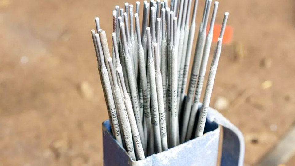
Image by castironwelding
Choosing Between Pure Nickel and Nickel-Iron Electrodes
Electrode selection determines both the mechanical properties of the deposit and the amount of preheat the casting can tolerate.
When ENi-CI (99 % Nickel) Is the Better Choice
Pure-nickel electrodes produce the softest, most machinable deposit. Even with high dilution the weld metal stays soft enough for conventional drills and taps. Use ENi-CI when the repair must be machined flush, when the casting is thin or lightly restrained, or when color match to gray iron is important.
Tensile strength is lower (typically 40–65 ksi) and the deposit is more expensive, so reserve it for precision work such as engine blocks, valve bodies, or decorative castings.
When ENiFe-CI (55 % Nickel) Delivers Better Performance
Nickel-iron electrodes give higher tensile strength (58–84 ksi range) and greater ductility under restraint. The iron content reduces the coefficient of expansion mismatch and improves tolerance to phosphorus and other impurities common in older castings.
ENiFe-CI is the preferred general-purpose rod for structural repairs, thick sections, ductile (nodular) iron, and joints between cast iron and mild steel. Machinability remains acceptable with carbide tooling provided dilution is kept moderate.
Cost and Availability Factors That Influence the Decision
ENiFe-CI costs substantially less per pound than pure nickel while covering most shop and field repairs. Many manufacturers list both classifications under the same brand line; check the AWS A5.15 designation on the packaging rather than marketing names.
For multipass build-ups, some operators butter the joint faces with ENi-CI and fill with ENiFe-CI to balance machinability and economy.
Preparing the Joint Surface and Crack Ends
Surface condition and joint geometry control dilution and residual stress more than most operators realize.
Cleaning Contaminants That Cause Porosity
Cast iron often contains oil, grease, or graphite that must be removed before any arc is struck. Degrease with solvent, then heat the area gently with a torch to drive residual hydrocarbons out of the pores.
Wire-brush or grind until bright metal appears. Residual graphite or scale increases the risk of porosity and fusion-line defects even with nickel filler.
Groove Design and Stop-Hole Practice
Grind or arc-air the crack into a U- or V-groove with a root radius. Sharp corners concentrate stress. Drill ⅛-inch stop holes at each end of the crack, slightly beyond the visible tip, to prevent propagation during welding.
On through-cracks, prepare both sides when access allows. Keep the groove as narrow as practical to minimize the volume of expensive nickel metal required.
Preheating Decisions Based on Section Thickness and Restraint
Preheat reduces the temperature gradient that drives cracking, but excessive heat can create new metallurgical problems.
Temperature Ranges for Gray Iron Versus Ductile Iron
Gray iron typically benefits from 400–600 °F (200–315 °C) preheat on medium sections. Ductile and malleable irons can often start lower, sometimes 200–400 °F. Heavy castings or highly restrained joints may require the upper end of the range or even 700 °F, applied uniformly.
Use temperature-indicating crayons or an infrared thermometer at multiple points; surface temperature alone is not enough on thick walls.
When Cold Welding With Nickel Rods Is Acceptable
Small, thin, or lightly loaded castings can be welded without preheat if pure-nickel electrodes and very short beads are used. The low heat input and ductility of the nickel deposit often absorb the stresses.
Once wall thickness exceeds roughly ⅜ inch or the part is clamped rigidly, preheat becomes the safer default. Monitor interpass temperature so the casting never cools below the original preheat value between beads.
Amperage, Polarity, and Arc Control for Minimum Heat Input
Nickel rods run at lower currents than steel electrodes of the same diameter. Excess amperage increases dilution and widens the brittle heat-affected zone.
Recommended Current Ranges by Electrode Diameter
For 3/32-inch (2.4 mm) electrodes the practical window is roughly 40–70 A for ENi-CI and 45–80 A for ENiFe-CI. For 1/8-inch (3.2 mm) electrodes use 70–100 A (ENi-CI) or 70–110 A (ENiFe-CI) in the flat position.
Reduce current 10–20 A for vertical and 5–15 A for overhead. Always start at the low end of the manufacturer’s range and increase only enough to maintain a stable arc and continuous fusion at the toes.
Polarity Selection and Its Effect on Penetration
Most nickel cast-iron electrodes are formulated for DC electrode positive (DCEP) or AC. DCEP gives a stable arc and moderate penetration. Some operators switch to DC electrode negative on surfacing passes to reduce penetration and dilution further.
Avoid high arc-force or hot-start settings; the extra energy raises heat input without improving fusion quality on cast iron.
Bead Sequence and Mechanical Stress Relief During Welding
The physical arrangement of beads and the use of peening determine whether residual stresses remain below the fracture threshold.
Short-Bead and Skip-Welding Patterns
Deposit beads no longer than 1–2 inches (25–50 mm). Move to a different location on the joint before depositing the next bead so heat dissipates. Back-step or skip sequences keep the overall temperature distribution more uniform. Continuous long beads create cumulative shrinkage that the brittle parent metal cannot tolerate.
Peening While the Bead Is Still Hot
Immediately after each short bead, lightly peen the deposit with a ball-peen hammer or pneumatic tool while the metal is still plastic. Peening stretches the weld metal and offsets the tensile stresses that form on cooling.
Over-peening can work-harden the surface or crack the deposit; light, overlapping blows are sufficient. Clean slag thoroughly between passes so subsequent beads fuse cleanly.
Post-Weld Cooling and Final Inspection Criteria
Cooling rate is the last controllable variable that decides success or failure.
Controlled Slow Cooling Methods
After the final pass, cover the entire casting with dry sand, vermiculite, or insulating blankets so it cools over several hours. Never quench with water or compressed air. For critical parts, a programmed furnace cool-down provides the most consistent results. Rapid cooling reintroduces the thermal gradients the entire procedure was designed to avoid.
Acceptable Versus Rejectable Defects After Cooling
Once the part reaches room temperature, inspect for surface cracks with dye penetrant or magnetic particle methods if the application is structural. Small slag inclusions or minor undercut can often be ground out and re-welded.
Fusion-line cracks or porosity that penetrate the thickness usually require the joint to be removed and the process restarted with adjusted preheat or electrode selection.
Wrapping Up
Successful cast-iron repair with nickel rods rests on three linked decisions: matching electrode type to the need for machinability versus strength, keeping heat input low through short beads and minimum amperage, and enforcing uniform preheat plus slow cooling.
When those parameters are controlled, even heavily restrained gray-iron castings can be restored without cracking.
Advanced operators further reduce risk on complex geometry by buttering the groove faces with pure nickel before filling with nickel-iron, creating a ductile transition layer that isolates the parent metal from the higher-strength fill passes.
FAQs
What amperage should I use for 1/8″ nickel rod on cast iron?
Start at 70–90 A on DCEP for either ENi-CI or ENiFe-CI and increase only until the arc is stable and the toes fuse cleanly. Lower the setting 10–15 A for vertical or overhead work.
Do I always need to preheat cast iron before using nickel rods?
No. Thin, lightly restrained sections can often be welded cold with pure-nickel electrodes and short beads. Medium and heavy sections, or any highly restrained joint, require 400–600 °F preheat for reliable results.
Which is better for engine block repair—Ni-99 or Ni-55?
Ni-99 (ENi-CI) is preferred when the repair must be machined or tapped afterward. Ni-55 (ENiFe-CI) is stronger and more economical for structural or non-machined areas of the same block.
Can I weld cast iron to mild steel with nickel rods?
Yes. ENiFe-CI is the standard choice for dissimilar joints because its expansion characteristics and strength accommodate both metals better than pure nickel.