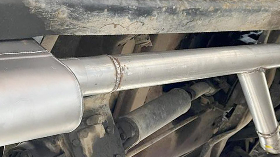
Copper pulls heat away from the joint so fast that the mild-steel side often fails to reach fusion temperature while the copper already melts or burns through. This mismatch produces incomplete fusion, porosity, or brittle zones when operators treat the joint like a standard steel weld.
Knowing how to weld copper to mild steel correctly matters because electrical bus bars, heat-exchanger tubes, grounding lugs, and repair work routinely demand a durable copper-steel transition.
The wrong process or filler leaves a joint that fails under thermal cycling or vibration. Proper filler selection, heat balance, and process choice turn an otherwise unreliable combination into a functional connection.
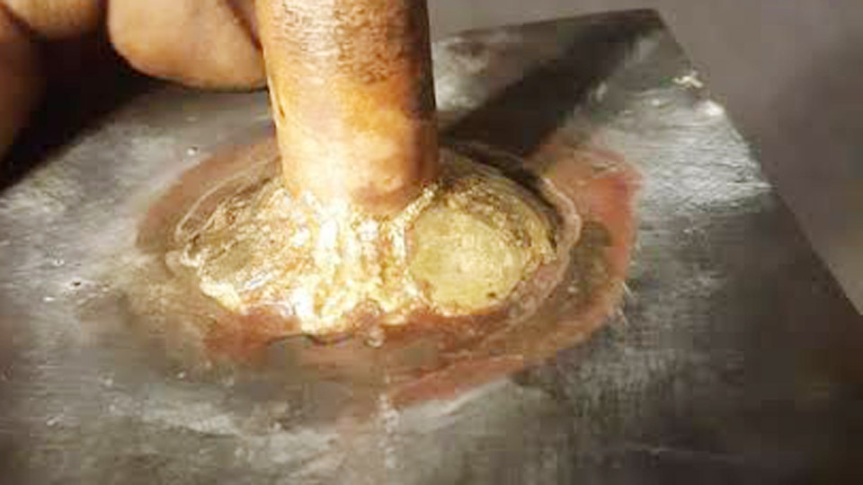
Image by r/Welding
Why Direct Fusion of Copper and Mild Steel Creates Metallurgical Problems
Copper’s thermal conductivity is roughly eight times that of mild steel. Heat introduced at the joint dissipates rapidly into the copper, starving the steel of the energy needed for full melting. Melting points differ by several hundred degrees—copper near 1085 °C versus mild steel above 1400 °C—so the copper reaches liquid state first.
Limited mutual solubility between iron and copper promotes segregation and, under certain cooling rates, liquid-metal embrittlement along steel grain boundaries. Thermal-expansion coefficients also differ, generating residual stresses that crack the joint during cooling if the weld metal lacks ductility.
Heat-Sink Behavior of Copper
On sections thicker than 3 mm the copper acts as a continuous heat sink. Without preheating the copper side to 200–400 °C, the arc energy is lost before a stable puddle forms on the steel. Thin sheet can sometimes be joined without preheat, but thicker plate almost always requires it.
Dilution and Intermetallic Risk
Excessive dilution of iron into a copper-rich weld pool produces hard, low-ductility zones. Silicon-bronze fillers limit this dilution better than pure copper rods because the silicon and manganese deoxidize the pool and improve wetting on both metals.
Selecting the Right Process: Fusion Welding Versus Brazing
Fusion welding melts both base metals and mixes them with filler. Brazing melts only the filler and relies on capillary flow and diffusion. For most non-critical or moderately loaded joints, brazing with a silver-bearing alloy produces higher reliability and less distortion.
Fusion methods become necessary when joint geometry prevents capillary action or when electrical conductivity must closely match pure copper.
When Silicon-Bronze Fusion Welding Is Appropriate
TIG or MIG with ERCuSi-A (silicon bronze) works for lap joints, fillets, and small butt joints under 6 mm thick where moderate strength and good corrosion resistance are required. The filler melts lower than pure copper, spreads well on steel, and tolerates some dilution.
When Silver Brazing Delivers Superior Joints
Silver alloys in the 45–56 % Ag range wet both copper and mild steel cleanly when the correct flux is used. Joint clearance of 0.05–0.13 mm allows capillary fill.
Brazed joints avoid the high residual stresses of fusion welding and retain more of the base-metal properties. This approach is preferred for pipe-to-flange connections and heat-exchanger tubes.
TIG Welding Copper to Mild Steel with Silicon Bronze
TIG provides the precise heat control needed to manage the conductivity difference. Use DCEN polarity, 100 % argon at 15–20 CFH, and a 2 % lanthanated or ceriated tungsten ground to a sharp point.
Machine Settings by Thickness
For 1.5–3 mm material start at 80–120 A. Thicker sections (3–6 mm) may need 120–180 A once the copper is preheated. Pulse capability helps keep average heat input low while still forming a fluid puddle. Foot-pedal control is essential because the copper side reaches melting temperature suddenly.
Joint Preparation and Fit-Up
Remove all oxides, oil, and mill scale from both surfaces with a stainless or bronze wire brush followed by solvent wipe. Bevel thicker steel edges 30–45° if full penetration is required. Keep root openings under 1.5 mm; larger gaps increase dilution and porosity. Clamp firmly to counteract differential expansion.
Torch Angle and Heat Distribution
Direct the arc primarily onto the copper until a small puddle forms, then wash the molten metal onto the steel edge. A 10–15° push angle with the torch favors copper. Add ERCuSi-A filler by dipping into the leading edge of the puddle rather than melting it in the arc.
Short stringer beads or short weave segments limit heat buildup. Allow interpass cooling so the copper does not overheat.
MIG Welding Options and Practical Limits
MIG with 0.9–1.2 mm silicon-bronze wire on pure argon or argon-helium mix can cover longer joints faster than TIG. Polarity is DCEP. Typical settings for 3 mm material fall in the 90–150 A range at 18–22 V. Spool guns or push-pull systems improve feeding of the soft bronze wire.
Heat control remains the limiting factor. The continuous arc tends to overheat thin copper, producing burn-through or excessive dilution.
MIG is therefore better suited to thicker sections or non-critical fabrication where appearance and ultimate strength are secondary. Test coupons are mandatory because parameter windows are narrower than for steel-to-steel MIG.
Preheating, Interpass Temperature, and Cooling Practice
Preheat the copper side with a neutral oxy-fuel or propane torch until it reaches a dull red in thicker sections (approximately 300–400 °C). Maintain interpass temperature below 150 °C on the steel side when possible to limit grain growth and residual stress.
Rapid quenching is undesirable; slow air cooling reduces the risk of cracking from differential contraction. For critical electrical joints, a light post-weld stress-relief cycle at 250–300 °C can improve ductility without softening the copper excessively.
Surface Cleanliness and Contamination Control
Copper is highly sensitive to oxygen, sulfur, and hydrocarbons. Any residual oxide or oil produces porosity that is difficult to eliminate once the weld solidifies. After mechanical cleaning, wipe both surfaces with acetone or alcohol immediately before welding.
Change to a clean bronze brush dedicated to copper; steel-wire brushes transfer iron particles that become inclusions. Shielding-gas coverage must remain unbroken—any draft that disrupts the argon envelope allows oxidation of the copper surface and subsequent porosity.
Joint Designs That Improve Success Rates
Lap joints and fillet configurations give the largest contact area and allow the operator to favor heat on one side. Butt joints require careful beveling of the steel and often a copper backing bar to support the molten pool.
For pipe-to-plate connections, a socket or lap design is far more forgiving than an open-root butt. When electrical conductivity is critical, maximize the copper cross-section in the joint and minimize the volume of bronze filler, because silicon bronze has lower conductivity than pure copper.
Evaluating Joint Quality and Common Defect Indicators
A successful weld shows continuous wetting on both the copper and steel toes without undercut on the steel or excessive convexity. Fracture testing of sample coupons should produce ductile failure through the copper or the bronze rather than along the interface. Porosity concentrated on the copper side usually indicates inadequate preheat or contaminated surfaces.
Cracking parallel to the fusion line on the steel side signals excessive iron dilution or rapid cooling. Visual inspection plus a simple bend or tensile test on scrap of the same thickness confirms the procedure before production parts are welded.
Wrapping Up
Choosing silicon-bronze TIG for precision work or silver brazing for capillary joints remains the most reliable path for copper-to-mild-steel connections. Heat balance, surface cleanliness, and filler selection decide whether the joint survives thermal cycling and mechanical load.
Advanced operators further improve consistency by using pulsed TIG at low frequency combined with differential preheating that raises only the copper side, keeping the steel cooler and reducing residual stress while still achieving full wetting.
Can you TIG weld copper directly to mild steel without filler?
Direct autogenous fusion is unreliable because of the large difference in melting points and limited solubility. A compatible filler such as ERCuSi-A is required to bridge the metallurgical gap and produce a usable joint.
What is the best filler metal for welding copper to steel?
ERCuSi-A silicon bronze is the most practical choice for TIG and MIG. It wets both metals, tolerates moderate dilution, and provides better strength and ductility than pure copper filler.
Do I need to preheat when welding copper to mild steel?
Yes for sections thicker than about 3 mm. Preheat the copper side to 200–400 °C so the heat sink effect does not prevent fusion on the steel. Thin sheet may sometimes be welded without preheat if heat input is carefully controlled.
Is brazing stronger than welding for copper-to-steel joints?
For many applications silver brazing produces a more consistent and ductile joint because it avoids the high residual stresses and intermetallic risks of fusion welding. Fusion methods are chosen mainly when geometry or conductivity requirements preclude brazing.