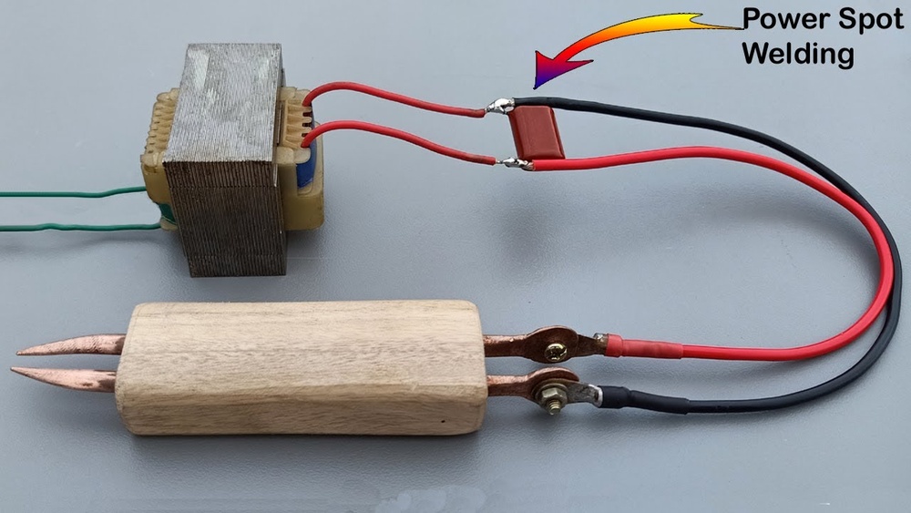
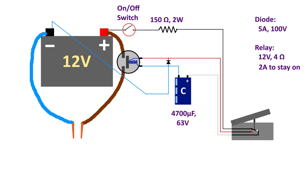
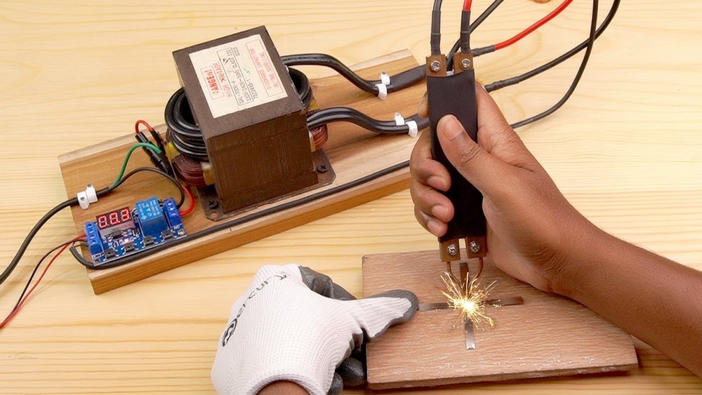
Many DIYers and hobbyists struggle with joining thin sheet metal, battery tabs, or small brackets securely without distortion, burn-through, or the high cost of commercial resistance welders. A homemade spot welder addresses this by delivering precise, high-current pulses for clean, localized fusion.
Learning how to make a homemade spot welder empowers precise control over weld strength on materials from 0.1mm nickel strips to 1-2mm mild steel, all at a fraction of professional equipment prices.
I’ll discuss the practical, real-world details on sourcing, modifying, and operating a transformer-based unit, with insights into electrode design, pulse control, and performance trade-offs.
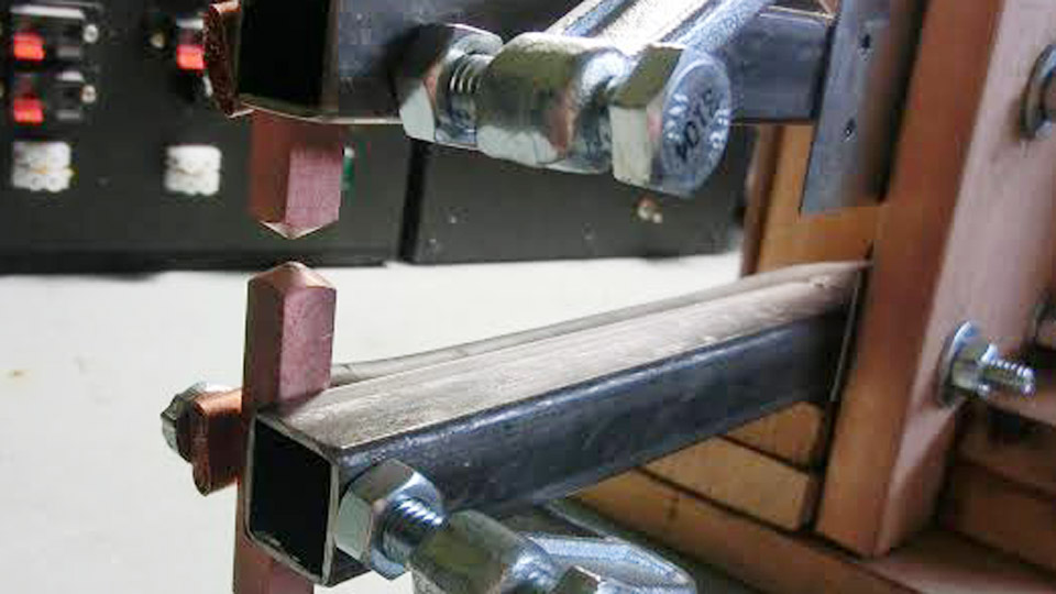
Image by exrockets
Why Spot Welding Matters for DIY and Small-Scale Work
Resistance spot welding generates heat at the interface of two metals through high current and pressure, creating a strong nugget without filler material. Unlike arc welding, it minimizes heat-affected zones, making it ideal for thin materials where warping is a concern.
A well-built homemade unit outputs hundreds to thousands of amps at low voltage (typically 2-5V), sufficient for consistent welds on automotive panels, battery packs, or metal fabrications.
Key advantages include speed, repeatability, and low distortion. Limitations appear with thicker materials (>2mm) or highly conductive alloys without sufficient power. Understanding these trade-offs guides component selection.
Sourcing and Preparing the Core: Microwave Oven Transformer (MOT)
Selecting the Right MOT
The foundation is a salvaged microwave oven transformer, typically from 700-1200W units. Higher-wattage models provide more core window space for heavy secondary windings. Test for intact primary windings (thick wire, fewer turns) and remove the high-voltage secondary (thin wire, many turns).
Prioritize transformers with separable shunts if possible, as they simplify disassembly. Avoid damaged cores with cracks or excessive rust. Multiple MOTs in parallel boost output for demanding applications, but single-unit builds suffice for most hobby use.
Disassembling Safely
Discharge the microwave’s high-voltage capacitor first using a resistor. Cut or chisel out the secondary winding carefully to preserve the primary and core laminations. Remove magnetic shunts if they restrict space, though some designs retain them for current limiting. Clean the core thoroughly.
Rewinding the Secondary for High Current
Replace the secondary with 2-4 turns of thick copper wire or cable (8-10 AWG or thicker, often doubled or tripled for lower resistance). Aim for output voltage around 2-5V under load and current exceeding 500-1000A peak. Use insulated high-strand-count cable or multiple parallel runs to handle heat and minimize voltage drop.
Calculate approximate turns based on core area and desired voltage. Test windings with a low-voltage supply initially. Secure turns tightly with insulation (fiberglass tape or high-temp varnish) to prevent shorts. Output voltage too high risks expulsion and weak welds; too low fails to fuse properly.
Electrode Design and Mechanical Assembly
Choosing Electrode Materials
Copper alloys dominate due to high conductivity and heat resistance. RWMA Class 2 (chromium-copper or chromium-zirconium-copper) balances conductivity (~80% IACS) and hardness for general use. For aluminum or coated steels, Class 1 offers higher conductivity. Harder Class 3 suits stainless or high-resistance materials.
Fabricating Electrodes and Arms
Use 8-12mm diameter copper rods, 10-15cm long. Shape tips to a slight dome or point (file or lathe) for current concentration without excessive sticking. Water-cooled electrodes extend life for production but add complexity for DIY.
Mount electrodes in arms or tongs for consistent pressure. Designs range from simple wooden or 3D-printed levers to scissor-style with springs. Pressure of 2-5 kg (depending on material thickness) ensures good contact resistance. Poor pressure causes arcing and surface damage; excessive crushes thin stock.
Common Mechanical Configurations
- Fixed bench-mounted with foot pedal for hands-free operation.
- Portable handheld tongs for field work.
- Adjustable gap for varying material thicknesses.
Incorporate a robust frame to handle magnetic forces during high-current pulses.
Control Systems: Timing and Power Management
Basic On/Off Switching
A heavy-duty contactor or relay rated for 20-40A+ switches the primary side. Direct switching works but lacks precision, leading to inconsistent nugget sizes.
Pulse Timing Circuits
Accurate pulse duration (10-200ms) prevents overheating. Simple timer modules (e.g., XY-J02) or Arduino-based controllers with potentiometers allow fine adjustment. NE555 monostable circuits generate precise short pulses for battery tab welding.
Dual-pulse modes improve results: a short pre-heat pulse cleans surfaces, followed by the main weld pulse. Zero-crossing or random-phase TRIAC control with snubbers (RC networks) protects against inductive spikes from the transformer.
Power and Safety Integration
Include a circuit breaker or fuse on the primary (15-20A typical). Ground the transformer core. Use thick, short secondary cables to reduce losses. Monitor temperature—transformers heat quickly during repeated use; add fans or duty cycle limits.
| Parameter | Typical Value | Notes |
|---|---|---|
| Primary Voltage | 220/110V AC | Match mains supply |
| Secondary Voltage | 2-5V | Under load |
| Peak Current | 500-2000A+ | Depends on winding and materials |
| Pulse Duration | 20-150ms | Adjust per thickness |
| Electrode Force | 2-10 kg | Higher for thicker stock |
Assembly, Wiring, and Initial Testing
Putting It Together
Mount the transformer in a non-conductive enclosure (wood or plastic) for safety. Route high-current secondary leads minimally. Connect control circuitry separately, often with a 12V or 5V supply for electronics. Ensure all connections use crimped lugs or heavy soldering to withstand vibration and heat.
Testing Protocol
Start with scrap material of known thickness. Clean surfaces thoroughly—mill scale, paint, or oxidation increases resistance unpredictably. Begin with short pulses and low duty cycles.
Observe nugget formation: a strong weld shows slight indentation and pulls a button on destructive testing. Adjust pulse time, pressure, or current (via additional turns or parallel MOTs) iteratively.
Measure output current indirectly with a shunt or clamp meter if available. Expect initial failures from poor contact or timing—refine based on results rather than fixed formulas.
Real-World Applications and Material-Specific Settings
For 18650 battery tabs (nickel strip ~0.15mm), use very short pulses (10-50ms) and light pressure to avoid burning through. Mild steel sheet (0.5-1mm) tolerates longer pulses (50-150ms) and higher force. Galvanized or coated materials require electrode material resistant to alloying (e.g., zirconium-copper) and possibly pre-cleaning.
Automotive repair benefits from spot welding for patch panels, preserving original appearance. Hobby electronics projects use it for custom battery packs. Limitations include unsuitability for aluminum without high power and clean surfaces, or very thick sections where heat input becomes impractical.
Troubleshooting Common Issues
- Weak welds: Increase current (more turns or better connections), pressure, or pulse time.
- Surface expulsion: Shorten pulse or reduce force.
- Overheating transformer: Improve duty cycle, add cooling, or use multiple units.
- Arcing: Ensure clean, flat contact and adequate pressure.
Alternatives to Transformer-Based Designs
Capacitor discharge (CD) welders store energy in supercapacitors or banks for precise, short bursts ideal for thin materials. They avoid continuous high mains draw but require charging time.
Battery-powered versions using lead-acid or Li-ion packs with MOSFET switching offer portability but demand careful current management. Commercial control boards simplify builds for specific tasks like battery assembly.
Each approach trades off cost, portability, and power capability. Transformer designs remain popular for their robustness and raw current delivery in workshop settings.
Performance Optimization and Advanced Considerations
Weld quality depends on the interplay of current, time, and force (the “heat equation” in resistance welding). Experimentation on your specific setup yields the best parameters, as wire resistance, electrode condition, and mains voltage vary. Track electrode wear—dress tips regularly to maintain geometry.
For pro-level results, integrate current sensing or closed-loop control, though this exceeds basic DIY needs. Consider power factor and inrush when scaling up; soft-start or larger service may be required.
Decision-Making Summary
A transformer-based homemade spot welder delivers reliable performance for most thin-metal and tab-welding tasks when built with attention to winding quality, electrode materials, and pulse precision. Match component ratings to your intended materials and workload—overbuilding for headroom prevents frustration.
The advanced insight: true expertise comes from understanding contact resistance dynamics, where minor surface preparation or force adjustments often outperform brute current increases. Test destructively on scraps, iterate parameters, and the result rivals commercial units for hobby and light professional use.
FAQ
How thick of metal can a homemade spot welder handle?
Most single-MOT designs reliably weld up to 1-1.5mm mild steel per side (total stack ~3mm). Thicker requires dual transformers, better cooling, or higher force. Test progressively—thicker stock demands longer pulses and risks distortion.
Is it safe to build and use a DIY spot welder?
With proper enclosure, grounding, fusing, and respect for mains voltage, yes. Always discharge capacitors, insulate high-current paths, and avoid operation near flammables. Novices should start with low-power tests.
What’s the cheapest way to make one?
Salvage an MOT, basic copper rods, heavy wire, and a simple timer module or contactor. Total cost under $50-100 excluding tools. Focus on robust mechanicals over fancy electronics initially.
Can I use it for battery pack building?
Yes—excellent for nickel strips on 18650/21700 cells with short, controlled pulses. Use pure copper or appropriate electrodes and practice on test tabs to dial in settings that avoid cell damage.