
How Much Voltage Is Required for Arc Welding is one of the most common questions welders ask, but the answer depends on the welding process, electrode type, material thickness, and machine settings.
Unlike amperage, which primarily controls heat input, arc voltage directly affects arc length, bead profile, penetration characteristics, and overall weld stability.
Using the wrong voltage can lead to excessive spatter, lack of fusion, undercut, or an unstable arc that compromises weld quality and increases rework.
Understanding the relationship between voltage and other welding parameters is essential for producing consistent, code-quality welds while avoiding unnecessary defects and wasted materials.
I’ll explain how arc welding voltage works, the typical voltage ranges for different welding processes, and the practical factors that determine the correct setting for reliable, high-quality results.
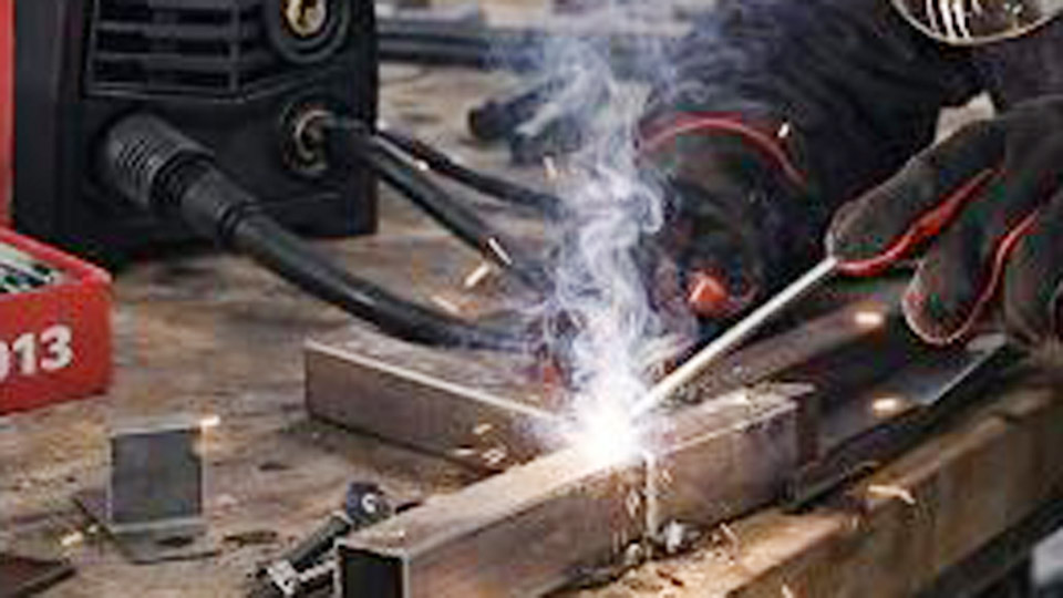
Image by arccaptain
Arc Voltage vs. Open Circuit Voltage (OCV)
Arc voltage refers to the voltage measured across the arc during welding. It typically falls in the 15–40 V range and is the operating voltage that sustains the plasma column and determines arc characteristics.
Open circuit voltage (OCV) is the no-load voltage present at the machine terminals before the arc is struck. It ranges from 50–100 V (commonly 50–80 V) and provides the higher potential needed to ionize the air gap and initiate the arc reliably. Once the arc establishes, voltage drops sharply to the operating arc voltage.
Why the difference matters: Low OCV makes arc starting difficult, especially with low-hydrogen electrodes or in challenging positions. Excessively high OCV raises safety risks without welding benefits. Standards limit maximum OCV for manual processes—typically 80 V AC or 100 V DC—to balance performance and operator safety.
In constant current (CC) processes like SMAW and GTAW, the welder controls arc voltage indirectly through arc length. In constant voltage (CV) processes like GMAW, the machine maintains a set voltage while current varies with wire feed speed.
Voltage Requirements by Welding Process
SMAW (Stick) Welding Voltage Settings
Stick welding uses a drooping characteristic power source. Arc voltage is not set directly on the machine but results from maintaining proper arc length—roughly equal to the electrode core diameter.
Typical operating arc voltages range from 20–35 V. For example:
- 6010/6011 electrodes: 20–25 V for deep penetration on mild steel.
- 7018 low-hydrogen: 22–28 V for smoother arcs and crack-resistant welds on thicker sections or critical joints.
OCV for SMAW machines is commonly 50–80 V. Higher OCV (closer to 70–80 V) improves arc initiation with difficult electrodes. Arc voltage increases with longer arc length, leading to wider beads, more spatter, and potential porosity. Short arcs produce narrower beads but risk electrode sticking.
For a 1/8-inch (3.2 mm) electrode on 1/4-inch mild steel, expect 20–26 V at correct arc length. Adjust amperage primarily for heat input, then fine-tune technique for voltage stability.
GMAW (MIG) Welding Voltage Settings
MIG operates on constant voltage. Voltage directly sets arc length and influences transfer mode. Typical ranges are 16–32 V, paired with appropriate wire feed speed (WFS).
- Short-circuit transfer (thin materials, all positions): 16–22 V. Ideal for 0.030-inch wire on sheet metal to minimize burn-through and spatter.
- Globular transfer: 22–28 V (transitional, higher spatter).
- Spray transfer (thicker materials, flat/horizontal): 24–32+ V with high argon mixes for smooth, high-deposition welds.
Example settings for mild steel with 0.035-inch ER70S-6 wire and 75/25 Ar/CO2:
- 1/8-inch thickness: ~19–22 V, 200–300 ipm WFS.
- 1/4-inch thickness: ~23–26 V for balanced penetration.
Voltage too low causes shorting and spatter; too high produces a long, unstable arc with undercut. Modern synergic machines simplify this by linking voltage and WFS to material thickness.
GTAW (TIG) Welding Voltage Settings
TIG requires the lowest arc voltages, typically 10–20 V, due to the non-consumable tungsten electrode and precise heat control.
- Mild steel/stainless: 12–18 V.
- Aluminum (AC): 14–20 V to break oxide layer effectively.
Arc length is critical—longer gaps increase voltage and risk tungsten contamination or instability. High-frequency start or lift-arc reduces reliance on high OCV. Foot pedal control allows real-time amperage adjustment while voltage remains relatively stable based on gap.
FCAW (Flux-Cored) Arc Welding
Flux-cored behaves similarly to MIG but often tolerates slightly higher voltages (18–30 V) due to the flux. Self-shielded wires may run on DCEN with different optimal ranges. Voltage settings depend on wire diameter and position—higher for overhead to control puddle.
Factors Influencing Required Voltage
Material Thickness and Type
Thicker materials generally require higher voltage for adequate penetration and bead width. Thin stock demands lower settings to avoid burn-through.
- Mild steel 1/16-inch: Lower voltages (16–20 V MIG).
- 1/2-inch+ plate: Higher voltages and amperage, often shifting to spray transfer.
Aluminum’s high thermal conductivity needs higher voltage settings or adjusted waveforms for oxide cleaning. Stainless steel benefits from tighter voltage control to manage heat input and prevent distortion or sensitization.
Electrode and Wire Selection
Electrode diameter and coating type dictate voltage:
- Smaller diameters need shorter arcs/lower voltages.
- Rutile vs. basic coatings affect arc characteristics and optimal voltage.
In MIG, wire diameter pairs with voltage: 0.023–0.030-inch for thin work (lower V), 0.035–0.045-inch for heavier (higher V).
Arc Length, Shielding Gas, and Position
Arc voltage rises almost linearly with arc length. Maintain consistent length for stability. Shielding gas affects ionization and arc voltage—pure argon lowers voltage needs compared to CO2 mixes. Out-of-position welding often requires lower voltage for better puddle control.
Polarity impacts effective voltage delivery: DCEP is standard for most processes, concentrating heat at the workpiece.
Machine Input Voltage and Power Considerations
Welding machines require specific input power:
- Home/hobby: 120 V for lighter duty (up to ~140–200 A).
- Shop/professional: 240 V or three-phase for higher output and duty cycle.
Input voltage affects maximum amperage and duty cycle but not the output arc voltage directly. Inverters offer better efficiency and multi-voltage capability. Always match machine capacity to expected loads—overdrawing causes voltage drops and poor performance.
Advanced Topics: Transfer Modes and Waveform Control
In MIG, voltage determines transfer mode alongside current and gas:
- Short-circuit: Low voltage, frequent shorting.
- Spray: Higher voltage, fine droplet transfer for superior bead appearance.
Pulsed MIG uses varying voltage/current waveforms to reduce average heat input while maintaining spray-like transfer—valuable for thin or heat-sensitive materials.
Modern machines with waveform control (e.g., surface tension transfer or controlled short-circuit) optimize voltage dynamically for reduced spatter and improved out-of-position performance.
Troubleshooting Voltage-Related Weld Defects
- Unstable arc / frequent extinguishing: Increase OCV or shorten arc length; check connections.
- Excessive spatter: Voltage too high or too low relative to WFS; adjust balance.
- Undercut or convex beads: Fine-tune voltage—lower for flatter profiles.
- Porosity: Long arc (high voltage) draws in contaminants; maintain short, consistent arc.
- Poor penetration: Increase voltage/amperage or switch transfer mode.
Monitor machine displays for actual voltage under load, as settings can drift with cable length or poor grounding.
Real-World Decision Framework for Voltage Selection
Select voltage based on:
- Process and equipment type.
- Material and thickness (reference manufacturer charts initially).
- Desired bead profile and mechanical properties.
- Test on scrap: Run a short bead, inspect for fusion, profile, and defects, then adjust by 0.5–1 V increments.
Prioritize amperage for heat/penetration and voltage for arc characteristics. Document successful settings for repeatability on similar jobs.
Performance-based Takeaway
Correct voltage selection transforms welding from trial-and-error to predictable results. In production or critical applications, even small voltage optimizations—combined with proper technique—yield measurable gains in travel speed, deposition efficiency, and joint integrity.
Advanced users leverage inverter technology and pulse programs to push these limits further, achieving spray transfer at lower average heat inputs for distortion-sensitive work.
FAQ
What is the typical arc voltage for stick welding?
20–35 V during welding, depending on electrode type and arc length. Maintain arc length approximately equal to electrode diameter for optimal results.
How does MIG voltage differ from stick welding?
MIG uses preset constant voltage (usually 16–32 V) that controls arc length directly, while stick relies on manual arc length control. MIG voltage also determines metal transfer mode.
Can I use a 120V machine for all arc welding tasks?
For light-duty work on thinner materials yes, but heavier fabrication or thicker sections benefit from 240V input for higher amperage, better duty cycle, and stable voltage output.
What OCV is best for reliable arc starting?
50–80 V provides easy starts without excessive safety risk. Lower values struggle with certain electrodes; higher values are available but require caution.


