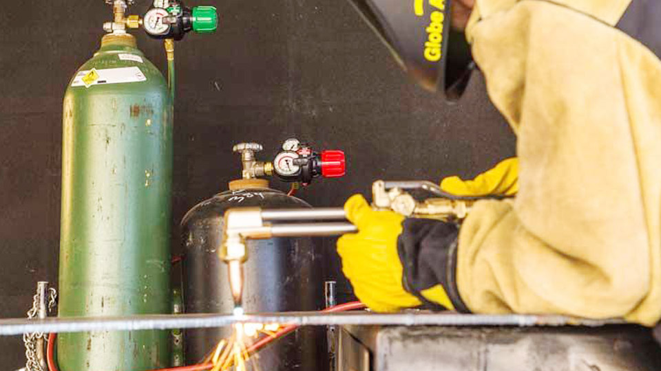
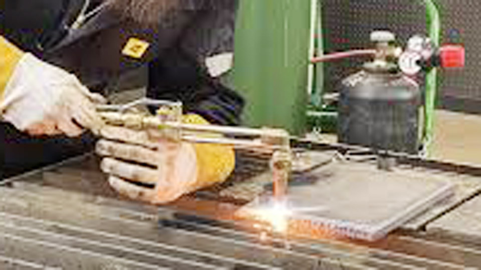
Inconsistent heat control remains the most common failure when operators attempt gas welding on mild steel. The puddle either freezes before fusion occurs or expands too rapidly and burns through thin sections.
Learning how to weld with an oxy-acetylene torch requires matching tip orifice size, regulator pressures, flame chemistry, and travel direction to the exact thickness and joint type.
Incorrect combinations produce brittle deposits, excessive oxidation, or incomplete penetration that cannot be corrected by later grinding.
Proper parameter selection delivers controllable heat input, clean fusion, and predictable bead profiles without the arc force or electrical variables of stick or MIG processes.
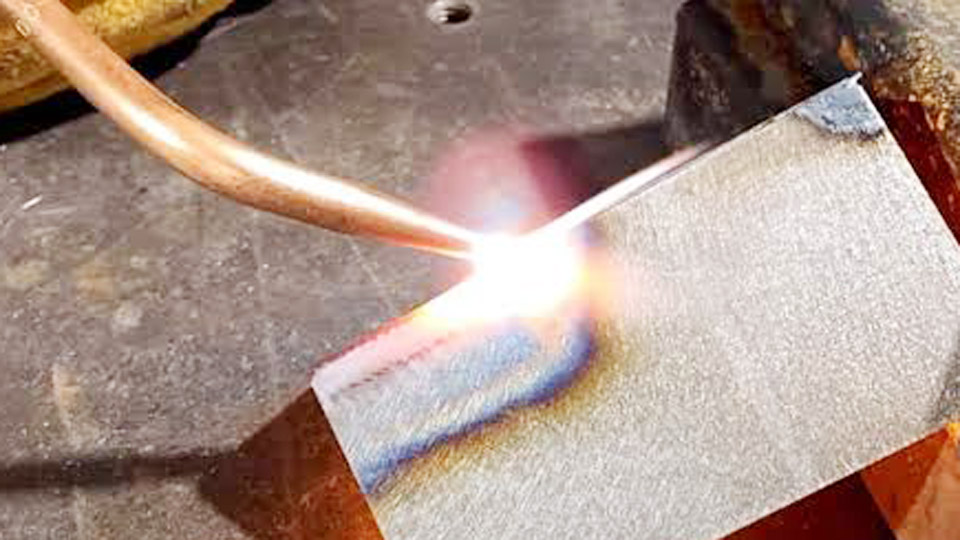
Image by roadkillcustoms
Matching Tip Size and Regulator Pressures to Metal Thickness
Tip orifice diameter and gas delivery rates determine total heat output more than any other single variable. Manufacturers publish orifice drill sizes and corresponding pressure ranges that keep the flame stable and the inner cone length proportional to the work thickness.
Victor-Style Welding Tip Chart for Mild Steel
| Metal Thickness | Tip Size | Oxygen Pressure (psig) | Acetylene Pressure (psig) | Approximate Orifice Drill |
|---|---|---|---|---|
| Up to 1/32″ | 000 | 3–5 | 3–5 | 75 (.022″) |
| 1/16″–3/64″ | 00 | 3–5 | 3–5 | 70 (.028″) |
| 1/32″–5/64″ | 0 | 3–5 | 3–5 | 65 (.035″) |
| 3/64″–3/32″ | 1 | 3–5 | 3–5 | 60 (.040″) |
| 1/16″–1/8″ | 2 | 3–5 | 3–5 | 56 (.046″) |
| 1/8″–3/16″ | 3 | 4–7 | 3–6 | 53 (.060″) |
| 3/16″–1/4″ | 4 | 5–10 | 4–7 | 49 (.073″) |
| 1/4″–1/2″ | 5 | 6–12 | 5–8 | 43 (.089″) |
Acetylene delivery must never exceed 15 psig at the regulator. Higher pressures risk unstable flow and flashback. Oxygen pressure is set only high enough to produce a clear inner cone once the acetylene valve is opened and the flame is balanced.
Longer hoses or flashback arrestors may require a modest pressure increase (up to 25 %) to compensate for flow restriction.
Decision Rules for Pressure Adjustment
Begin at the low end of the published range for the selected tip. Open the acetylene torch valve first, ignite, then introduce oxygen until the feather disappears. If the inner cone becomes too short or the flame lifts from the tip face, raise both regulators equally in 1 psig increments.
If the cone elongates and becomes soft, reduce acetylene slightly. The goal is a sharply defined, stable inner cone whose length approximates the metal thickness being welded.
Setting Flame Chemistry for the Base Metal
Flame type controls the chemical interaction between the gas envelope and the molten pool. Three distinct settings exist, each identified by visual markers at the tip.
Neutral Flame Characteristics and Use
Equal volumes of oxygen and acetylene produce a neutral flame. The inner cone is sharply defined and bluish-white; the outer envelope is lighter and longer. This setting neither adds carbon nor removes it from the weld pool.
It is the standard choice for mild steel, low-alloy steel, and most general fabrication. The puddle remains quiet and free of excessive sparking or boiling.
Carburizing (Reducing) Flame Application
A slight excess of acetylene creates a carburizing flame. A secondary feather appears beyond the inner cone. The added carbon can slightly harden the deposit and is useful on certain cast irons or when a softer, more fluid pool is desired on non-ferrous metals.
Excess carburizing produces a sooty, carbon-rich deposit that reduces ductility on mild steel and should be avoided for structural work.
Oxidizing Flame Limitations
Excess oxygen shortens the inner cone and produces a harsh, hissing sound. The oxidizing flame is reserved for brass and some copper alloys where the oxide layer aids flow. On mild steel it causes excessive sparking, porous deposits, and rapid oxidation of the filler. Operators rarely use an oxidizing flame for carbon-steel welding.
Choosing Leftward or Rightward Technique by Thickness
Travel direction relative to the filler rod changes heat distribution and penetration profile. The choice is driven almost entirely by plate thickness.
Leftward (Forehand) Technique for Sheet and Light Plate
Used on material up to approximately 3/16″ (5 mm). The torch moves from right to left with the flame pointing ahead of the completed weld. Torch angle is typically 60–70° to the plate surface; the filler rod is held at 30–40°.
The flame preheats the joint edges while the operator adds filler into the leading edge of the puddle. Circular or slight side-to-side motion of the torch maintains fusion on both sides of the joint. This method gives excellent visibility of the puddle and is preferred for sheet-metal edge welds and thin butt joints.
Rightward (Backhand) Technique for Heavier Sections
Recommended above 3/16″. Travel proceeds from left to right. The torch trails the filler rod so the flame is directed onto the completed weld and the molten pool. Torch angle drops to 40–50°. The flame provides post-heat that slows cooling and improves fusion on thicker sections.
Plates thicker than 5/16″ usually receive a 30° bevel on each edge to form a 60° included angle. The rightward method deposits a narrower, more reinforced bead and reduces the risk of incomplete penetration on heavier material.
All-Position Rightward Adaptation
For vertical and overhead pipe or plate, a modified rightward technique keeps the puddle supported by the force of the flame. Travel speed increases slightly and filler addition becomes more intermittent to prevent sagging. The same 40–50° torch angle is retained, but the operator works in short segments, allowing each section to freeze before progressing.
Filler Rod Selection and Feeding Technique
Filler metal diameter and chemistry must match both base-metal thickness and the heat available from the selected tip.
Diameter Matching Rules
A practical starting rule is filler diameter equal to or slightly less than plate thickness. Common mild-steel gas-welding rods (RG45 or equivalent) are supplied in 1/16″, 3/32″, 1/8″, and 5/32″ diameters.
On 1/8″ plate a 3/32″ or 1/8″ rod works well. Excessively large filler absorbs too much heat and freezes the puddle; undersized filler requires rapid feeding and can produce undercut.
Feeding Motion and Dip Technique
The rod tip remains in the outer flame envelope until needed, then is dipped into the leading edge of the puddle. Continuous immersion contaminates the rod with oxide and produces inclusions. A rhythmic dip-and-withdraw motion maintains a clean tip and controlled addition rate.
In leftward welding the rod leads the torch; in rightward welding the rod follows. Rod angle stays consistent with the technique chosen—approximately 30–40° to the work surface.
Joint Design and Edge Preparation Decisions
Edge condition and joint geometry dictate both tip size and technique selection.
Square-Edge Butt Joints
Suitable up to 1/8″ without bevel when leftward technique and a neutral flame are used. A slight gap (approximately half the plate thickness) allows full penetration. Larger gaps require more filler and increase the chance of burn-through on thin material.
Beveled Joints for Thicker Plate
Above 3/16″ a single-V or double-V preparation with 30° bevels per side produces a 60° included angle. Root face of 1/16″–3/32″ prevents melt-through while still allowing the flame to reach the root. Multi-pass sequences become practical; the first pass establishes the root, subsequent passes fill the groove using the same tip or one size larger.
Fillet and Lap Joints
Fillet welds on T-joints or lap joints require the flame to be directed more equally onto both members. Torch angle is adjusted so the inner cone equally heats the vertical and horizontal surfaces. Filler is added primarily to the root of the fillet to avoid excessive convexity.
Reading the Puddle and Making Real-Time Adjustments
Puddle appearance provides immediate feedback on heat balance, travel speed, and flame setting.
Indicators of Correct Heat Input
A quiet, fluid oval puddle with clean edges and minimal sparking signals proper parameters. The inner cone length remains stable and the slag (when present) floats freely to the surface. Bead width stays consistent at roughly two to three times the tip orifice diameter.
Correcting an Overheated Pool
When the puddle expands rapidly, edges undercut, or the metal begins to spark vigorously, reduce heat by increasing travel speed, shortening the flame (slightly lowering oxygen), or moving the inner cone farther from the surface. On thin material the torch may be lifted momentarily to allow the pool to freeze before continuing.
Correcting an Insufficient Pool
A sluggish, high-crowned puddle that fails to wet the base metal indicates low heat. Slow the travel speed, lengthen the flame slightly, or bring the inner cone closer to the work. Adding filler too early freezes the pool further; wait until the base metal is fully molten before introducing rod.
Position-Specific Heat Management
Gravity and heat sinking change the required balance of flame force and travel speed.
Flat Position Baseline
Maximum control and highest deposition rates occur in the flat position. Standard tip sizes and the pressures listed earlier apply directly. Both leftward and rightward techniques function without modification.
Vertical and Overhead Adjustments
Vertical-up travel uses a slightly smaller tip or reduced pressure to keep the puddle size manageable. Short, rhythmic advances of the torch and intermittent filler addition prevent runoff.
Overhead work demands the shortest practical arc (inner cone almost touching the work) and faster travel so the metal freezes before it can drip. Rightward technique is preferred because the flame force helps support the molten metal against gravity.
Wrapping Up
Selecting tip size from the thickness chart, establishing a neutral flame, and choosing leftward or rightward travel according to plate thickness form the core decision sequence for successful oxy-acetylene welding. Once those three parameters are locked, puddle observation becomes the continuous feedback loop that keeps fusion consistent.
Advanced operators further refine results by deliberately varying the distance of the inner cone from the surface mid-pass—closing the distance for deeper root penetration and withdrawing slightly to control reinforcement height—without changing regulator settings.
FAQs
What gas pressures should I use for oxy-acetylene welding 1/8″ mild steel?
Use a size 2 or 3 tip with oxygen and acetylene both set between 3–6 psig. Adjust upward only enough to produce a sharp neutral inner cone.
Is a neutral flame always required for mild steel?
Yes for structural and general fabrication work. A neutral flame neither adds nor removes carbon and produces the cleanest, most ductile deposit.
When should I switch from leftward to rightward welding technique?
Switch to rightward when plate thickness exceeds approximately 3/16″. The backhand method improves penetration and reduces the risk of incomplete fusion on heavier sections.
What diameter filler rod works best with a size 3 welding tip?
A 3/32″ or 1/8″ mild-steel gas-welding rod (RG45 or equivalent) matches the heat output of a size 3 tip on 1/8″–3/16″ material.