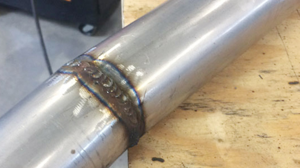
Carbide precipitation and loss of corrosion resistance appear quickly when heat input stays too high or shielding gas introduces excess carbon during MIG welding of 304 stainless.
Learning how to MIG weld 304 stainless steel correctly prevents chromium carbide formation along grain boundaries, keeps the weld and HAZ corrosion-resistant, and limits distortion caused by the alloy’s higher thermal expansion.
The process demands tighter control of voltage, wire speed, travel speed, and gas composition than mild steel because stainless conducts heat more slowly and freezes faster, producing a sluggish puddle that resists wetting.
Accurate filler selection, low-CO₂ gas mixes, and disciplined heat management deliver sound, corrosion-resistant joints on sheet, plate, and structural components.
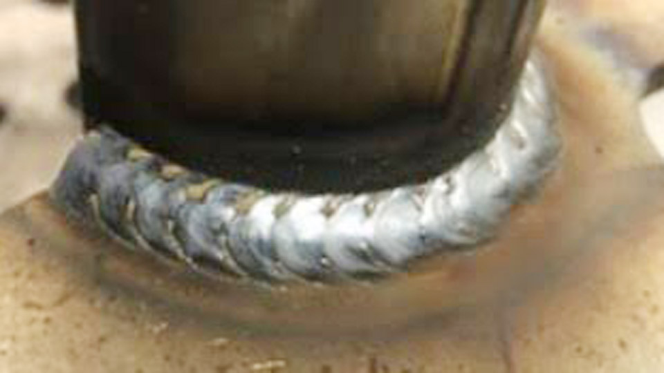
Image by megmeet-welding
Choosing the Correct Filler Metal for 304 Base Material
Matching chemistry and carbon content protects the corrosion performance of the finished weld.
ER308L Versus ER308LSi Selection
ER308L is the standard matching filler for 304 and 304L. The “L” designation keeps carbon at or below 0.03 %, minimizing the risk of sensitization. ER308LSi adds higher silicon, which improves puddle fluidity and wetting on the sluggish stainless pool.
Most fabricators prefer the Si version for short-circuit and pulsed transfer because it reduces the ropey bead appearance common with standard 308L.
When 309L Becomes the Better Choice
Use 309L or 309LSi only when joining 304 to carbon or low-alloy steel. The higher chromium and nickel content accommodates dilution from the mild-steel side and maintains adequate corrosion resistance in the mixed fusion zone. For pure 304-to-304 joints, stay with 308L/308LSi.
Shielding Gas Selection That Preserves Corrosion Resistance
Gas composition directly affects carbon pickup, arc stability, and bead shape.
Tri-Mix for Short-Circuit Transfer
The classic short-circuit mix—90 % helium, 7.5 % argon, 2.5 % CO₂—supplies high thermal conductivity that flattens the bead and improves fusion into the sidewalls. Helium counters the cold, sluggish nature of stainless, while the low CO₂ content limits carbon increase in the weld metal.
Argon-Based Alternatives
98 % argon + 2 % CO₂ or 98 % argon + 2 % oxygen produce acceptable results at lower cost and wider availability. These mixes run colder than tri-mix and require slightly higher voltage to achieve comparable wetting. Keep active gas additions at or below 2–3 %; higher CO₂ levels raise carbon content and degrade corrosion resistance.
Gases to Avoid
75/25 argon-CO₂ or 100 % CO₂ introduce excess carbon and oxygen that oxidize chromium and reduce the passive film. Pure argon yields unstable arc starts and poor wetting in the MIG process.
Machine Settings and Transfer Mode Decisions
Stainless requires different voltage and wire-feed relationships than carbon steel because of higher electrical resistivity.
Short-Circuit Parameters for Sheet and Thin Plate
For 0.030″ ER308LSi on 16-gauge to 1/8″ material, typical starting points are 17–21 V and 180–280 ipm wire speed with tri-mix or 98/2 gas. Contact-tip-to-work distance stays short—⅜” to ½”—to maintain arc stability.
Stainless produces lower amperage at the same wire speed than mild steel, so expect to increase wire feed slightly above mild-steel charts while raising voltage for better wetting.
Spray and Pulsed Spray on Thicker Sections
Spray transfer needs argon-rich gas (98 % Ar + 1–2 % O₂) and higher energy: roughly 24–28 V and correspondingly higher wire speeds for 0.035″ wire. Pulsed MIG lowers average heat input while still achieving spray-like transfer, making it the preferred mode for out-of-position work and distortion-sensitive assemblies.
Many modern machines offer stainless-specific pulsed programs that automatically manage background and peak current.
Inductance and Arc Control Adjustments
Increasing inductance lengthens the short-circuit cycle and softens the arc, helping the puddle flow to the toes and reducing the ropey profile characteristic of stainless. On machines without inductance control, voltage and travel-speed adjustments become the primary tools for bead shape.
Joint Preparation and Contamination Control
Cross-contamination from carbon steel tools destroys corrosion resistance faster than most other process errors.
Dedicated Tooling Requirements
Use only stainless-steel wire brushes, grinding wheels, and cutting discs that have never contacted carbon steel. Residual iron particles embedded in the surface create rust initiation sites after welding. Clean the joint to bright metal, removing oils, paint, and scale. Acetone or dedicated stainless cleaners remove residual contaminants without leaving films.
Fit-Up and Root Opening
Maintain tight, consistent fit-up. Excessive gaps increase heat input and the volume of filler required. For open-root joints on thicker plate, a small consistent gap combined with short-circuit or pulsed transfer produces reliable root fusion without burn-through.
Heat Input Management and Distortion Control
Austenitic stainless expands approximately 50 % more than carbon steel and conducts heat more slowly, concentrating thermal stress in the weld zone.
Interpass Temperature Limits
Keep interpass temperature below 300 °F (150 °C) on multi-pass welds. Higher temperatures extend time in the sensitization range (approximately 800–1500 °F), allowing chromium carbides to form and depleting corrosion resistance in the HAZ. Use temperature-indicating crayons or infrared measurement between passes.
Travel Speed and Stringer Technique
Favor stringer beads over wide weaves. A consistent push (forehand) angle of 5–15° produces a flatter bead and better shielding coverage. Travel fast enough to limit heat input while still achieving complete fusion at the toes. Excessive dwell time or slow travel increases distortion and the risk of carbide precipitation.
Back-Purging for Full-Penetration Joints
On pipe or critical butt joints, argon back-purging prevents sugaring (heavy oxidation) on the root side. Maintain purge flow until the root has cooled below the oxidation temperature. For non-critical sheet work, skip purge only when the root will be ground or is non-wetted in service.
Drive Rolls, Liner, and Torch Setup Specific to Stainless Wire
Stainless wire is harder and more abrasive than mild-steel wire.
Knurled Drive Rolls and Dedicated Liners
V-knurled drive rolls grip the harder stainless wire more reliably than smooth V-groove rolls. Install a liner sized exactly to the wire diameter and dedicated to stainless to prevent carbon-steel residue contamination. Check contact tips frequently; stainless wire accelerates tip wear.
Stick-Out and Gas Flow Rates
Maintain ⅜”–½” stick-out for short circuit and slightly longer for spray. Gas flow typically runs 20–30 cfh depending on nozzle size and air movement. Post-flow of 0.5–3 seconds after the arc extinguishes protects the solidifying puddle from atmospheric nitrogen and oxygen.
Troubleshooting Common Weld Appearance and Defect Issues
Ropey or Convex Bead Profile
Increase voltage or inductance, switch to Si-bearing wire, or move to a higher-helium gas mix. Slow travel exacerbates the problem by allowing the puddle to freeze before it can wet out.
Excessive Spatter or Unstable Arc
Check gas coverage, reduce stick-out variation, and verify that active gas content remains low. Contaminated wire or liner often produces erratic feeding that appears as arc instability.
Discoloration and Loss of Corrosion Resistance
Heavy straw or blue discoloration beyond the immediate HAZ signals excessive heat input. Reduce amperage/voltage, increase travel speed, and verify interpass temperature. Post-weld cleaning with a stainless brush or pickling paste restores the passive layer when discoloration is limited.
Wrapping Up
Selecting 308LSi wire, a low-CO₂ shielding gas, short-circuit or pulsed parameters matched to thickness, and strict heat-input limits produces corrosion-resistant, low-distortion welds on 304 stainless.
The single highest-leverage decision remains gas and filler combination: once those are correct, voltage and travel speed become the primary tools for bead shape and mechanical integrity.
Advanced operators further reduce residual stress by sequencing welds to balance heat and by using pulsed programs that keep average heat input low while still achieving complete fusion on production parts.
FAQs
What shielding gas is best for MIG welding 304 stainless?
Tri-mix (90 % He / 7.5 % Ar / 2.5 % CO₂) gives the best wetting and bead shape for short circuit. 98 % Ar / 2 % CO₂ is a practical lower-cost alternative.
What wire should I use for 304 stainless MIG?
ER308L or ER308LSi. The Si version improves puddle fluidity. Use 309L only when joining 304 to carbon steel.
Can I MIG weld 304 stainless with regular C25 gas?
It is possible but not recommended. High CO₂ raises carbon in the weld and reduces corrosion resistance. Limit active gas to 2–3 %.
What is the maximum interpass temperature for 304 stainless?
Keep interpass below 300 °F (150 °C) to minimize time in the sensitization range and preserve corrosion resistance.