Pull the trigger, hear the wire feed, and get nothing—or only a weak, sputtering spark that refuses to sustain. A MIG welder not arcing properly stops work immediately and points to a break in the electrical circuit rather than a complete machine failure.
The arc requires clean conductivity from the power source through the contact tip, across the short gap to the workpiece, and back through the ground clamp. Any resistance spike, polarity error, or voltage drop below the ignition threshold kills the arc before it stabilizes.
Identifying the exact interruption—ground path, tip condition, polarity, or settings—restores reliable starts and prevents repeated burn-back or porosity that ruin joints on mild steel, stainless, or aluminum.
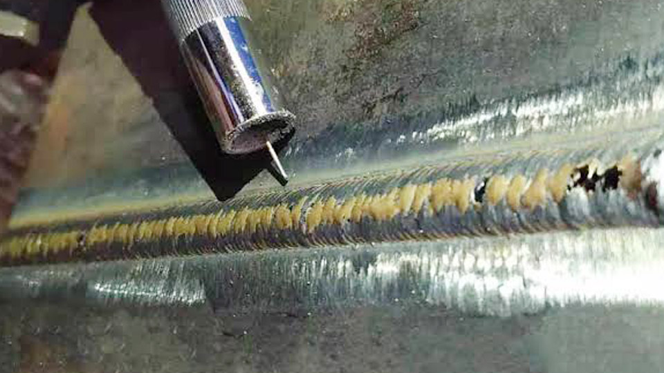
Image by perfectwelders
Why the Arc Fails When Wire Feeds Normally
Wire feed confirms the trigger, drive motor, and liner path function. The missing arc means welding current never reaches the wire tip or cannot complete the circuit.
Ground Path Resistance and Clean Metal Requirements
The work clamp must bite bare metal. Paint, rust, mill scale, oil, or powder coating creates enough resistance to drop effective voltage by 2–4 V or more, preventing arc initiation even when the clamp appears tight.
Clamp within 12–18 inches of the weld zone on clean, ground surfaces. Longer cable runs or clamps attached only to a painted table add measurable resistance. Inspect the clamp jaws for corrosion or flattened teeth; file or replace them if contact area is reduced.
Continuity checks with a multimeter (machine off) should show under 0.5 ohms from clamp to gun tip. Higher readings indicate frayed cable strands or loose lugs at the machine.
Contact Tip Conductivity Loss
The copper contact tip transfers current to the wire. Spatter buildup, oval wear, burn-back (wire fused inside the tip), or an oversized bore breaks consistent electrical contact.
Match tip ID exactly to wire diameter—0.030″ tip for 0.030″ wire, 0.035″ for 0.035″. Recess the tip 1/8–1/4″ inside the nozzle for gas coverage without shorting.
Replace tips after 50–100 hours of arc time or at the first sign of blue discoloration and pitting. A worn tip often produces intermittent sparks or forces the wire to arc inside the tip instead of at the workpiece.
Polarity Mismatch and Its Effect on Arc Initiation
Wrong polarity reduces arc force and can prevent ignition entirely, especially after switching wire types.
Solid Wire vs Flux-Cored Requirements
Gas-shielded solid wire (ER70S-6 and similar) requires DCEP—electrode (gun) positive, work clamp negative. This concentrates two-thirds of the heat at the workpiece for deeper penetration and stable starts. Self-shielded flux-cored wire typically needs DCEN—gun negative.
Reversed polarity on solid wire produces a soft, wandering arc with heavy spatter and frequent extinguishing. Confirm the wire manufacturer’s label; some dual-shield flux-cored wires also run DCEP.
How to Verify Polarity on Your Machine
Most machines have clearly marked positive and negative terminals or polarity jumpers inside the case. For external lead machines, the gun cable connects to the positive terminal for DCEP. On internal machines, check the polarity switch or board jumpers.
After any wire change, test on scrap: correct polarity yields a crisp start and steady hiss; incorrect polarity yields weak sputtering and poor wetting. Never assume factory settings remain correct after previous jobs.
Voltage, Wire Speed, and Stickout Decisions That Prevent Proper Arcing
Settings must supply enough open-circuit voltage to ionize the gap while matching wire feed to maintain the short-circuit or spray transfer mode.
Minimum Voltage Thresholds for Different Thicknesses
Voltage too low prevents the arc from establishing or sustaining. Typical short-circuit ranges for mild steel with 0.030–0.035″ wire:
- 22–24 gauge: 14–16 V
- 1/16–1/8″: 16–18 V
- 3/16–1/4″: 18–22 V
Open-circuit voltage (measured tip to ground with trigger pulled, no wire contact) should read in the machine’s specified range, often 18–32 V depending on the dial setting. If measured voltage under load drops sharply, check input power or cable gauge.
Wire speed must balance voltage—too high relative to voltage causes stubbing and push-off; too low causes burn-back into the tip.
Stickout Length Impact
Excessive electrode stickout (distance from tip to workpiece) increases resistance in the wire itself and reduces current at the arc. Maintain 3/8–1/2″ for short-circuit transfer on solid wire. Longer stickout lowers effective amperage, producing a cold, unstable arc that extinguishes easily.
Shorten stickout first when starts become hesitant, then fine-tune voltage and wire speed together on scrap of matching thickness.
Gun, Liner, and Cable Issues That Interrupt Current Flow
Mechanical restrictions or loose connections in the gun assembly stop current even when the machine outputs voltage.
Liner Drag and Bend Radius Effects
A kinked, dirty, or incorrectly trimmed liner creates intermittent wire contact and current interruption. Lay the gun cable as straight as possible and jog wire through it; resistance or jerky feed indicates liner problems.
Replace liners at the first sign of shavings or restricted feed, and trim to the manufacturer’s exact length so the liner seats fully against the contact tip. Excessive gun neck bend or a straight neck without sufficient contact points can also reduce conductivity—many guns perform better with a 45–60° neck.
Loose Connections at the Drive Block and Gun Plug
Power transfers through the gun plug and internal power pins. Vibration loosens these over time. Disconnect power, inspect the plug for burned pins or corrosion, and reseat firmly.
Check the connection at the drive roll assembly where the power cable attaches. A loose or oxidized connection produces voltage drop that appears as no arc or a weak spark only.
Input Power and Machine Output Verification
The machine may power the fan and feed motor yet deliver insufficient welding voltage under load.
Extension Cord and Circuit Capacity Limits
Undersized or long extension cords cause voltage drop at the machine. For 115 V units, use 10-gauge or heavier cord no longer than necessary. For 230 V machines above 180 A, avoid extensions when possible or use appropriately rated cable.
Measure input voltage at the receptacle under load; expect 110–120 V or 220–240 V within machine tolerances. Tripped breakers or shared circuits with other high-draw tools reduce available power and prevent arc formation.
Internal Output and Contactor Checks
If external connections check good, the contactor or output board may fail to close the welding circuit. Listen for the contactor click when the trigger is pulled. No click with power on and trigger closed points to a control or contactor issue.
Fault lights or error codes on digital machines often indicate thermal overload, primary voltage problems, or output faults. Thermal cutouts reset after cooling; repeated trips signal overheating from duty cycle abuse or restricted ventilation.
Systematic Decision Path for Restoring Arc Stability
Begin with the highest-probability external items that require no tools beyond a wire brush and spare tip. Clean and reposition the ground clamp on bare metal, replace or clean the contact tip, and confirm polarity matches the wire.
Next verify voltage and wire speed against the machine chart for the thickness and wire diameter, then reduce stickout. Only after these steps move to liner inspection, gun connections, and input power measurements.
Wrapping Up
Document the exact settings and conditions that restore a crisp start—this creates a baseline for future jobs and reveals patterns such as humidity-related corrosion or specific material coatings that repeatedly raise ground resistance.
When the arc initiates cleanly, sustains a steady hiss, and produces consistent short-circuit transfers without excessive burn-back, the circuit integrity is restored.
Advanced operators further stabilize performance by monitoring open-circuit voltage under load and maintaining contact tips to the manufacturer’s wear limit rather than waiting for visible failure, ensuring every start remains predictable across varying joint conditions and ambient temperatures.
FAQs
Why does my MIG welder feed wire but produce no arc?
Poor ground clamp contact on dirty or painted metal is the most frequent cause. Clean the clamp area to bare metal, tighten the clamp, and confirm the contact tip is clean and correctly sized for the wire.
What causes a weak or sputtering arc on a MIG welder?
Worn contact tip, mismatched voltage and wire speed, or excessive stickout. Replace the tip, raise voltage into the recommended range for the material thickness, and hold 3/8–1/2″ stickout.
Can wrong polarity stop a MIG welder from arcing?
Yes. Solid wire with gas requires DCEP. Running it on DCEN produces a weak or non-existent arc. Check and reverse the leads or jumpers according to the wire type.
How do I check if low input voltage is preventing the arc?
Measure voltage at the wall outlet under load with a multimeter. Values significantly below 110–120 V (or 220–240 V for dual-voltage machines) indicate cord, circuit, or supply problems that reduce welding output.