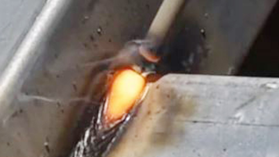
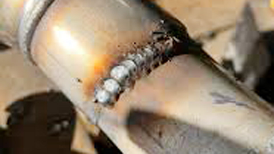
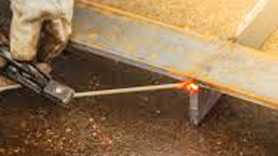
If you’re wondering why my welding rod keeps sticking, the problem usually points to an issue with amperage, electrode handling, machine settings, or the condition of the welding rod itself.
A sticking electrode doesn’t just interrupt your workflow—it can damage the rod coating, create poor arc starts, reduce weld penetration, and lead to weak or inconsistent welds that require costly rework.
Even experienced stick welders encounter this issue when welding thin material, using the wrong polarity, or working with damp electrodes. Identifying the root cause is essential for maintaining a stable arc and producing clean, reliable welds.
By understanding what causes electrodes to stick and how to correct each issue, you can improve arc control, reduce wasted rods, and achieve stronger, more consistent welding results on every project.
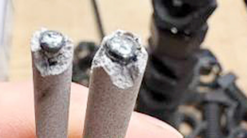
Image by ig/realsheetmetalsamurai
Amperage Too Low – The Primary Cause of Instant Freezing
Insufficient current remains the single most frequent reason an electrode sticks on contact. When amperage falls below the electrode’s operating range, the tip cannot generate enough heat to melt both the core wire and the base metal simultaneously. The result is a solid metallic bond instead of a sustained arc.
How Low Current Causes Immediate Sticking
At low amperage the electrode tip reaches melting temperature slowly. Contact with the cooler base metal rapidly conducts heat away, freezing the tip in place. The arc never establishes because the voltage collapses under the short-circuit condition and the machine cannot recover.
Miller and other manufacturers note that too-low current produces an especially sticky electrode during the strike and causes the arc to extinguish repeatedly even after it starts.
Finding the Correct Operating Range for Common Electrodes
A practical starting rule is one amp per 0.001 inch of electrode diameter. A 1/8-inch (0.125-inch) electrode therefore begins near 125 A. Manufacturer ranges refine this further:
- E6010 / E6011 1/8″: typically 80–130 A
- E6013 1/8″: 90–140 A
- E7018 1/8″: 90–160 A (often 110–140 A in practice)
Position also matters. Vertical and overhead work usually requires 10–15 % less current than flat to keep the puddle controllable. Start in the middle of the published range for the electrode and position, then adjust.
Adjusting in Small Increments Without Overheating
Raise current in 5–10 A steps while testing on scrap of the same thickness. The goal is a quiet, stable arc that starts cleanly and maintains a fluid puddle without undercut or excessive spatter. Once the rod no longer freezes on contact and the arc holds at the correct length, lock the setting.
Going significantly above the range creates its own problems—glowing electrode, undercut, and degraded flux performance—so incremental changes keep the process inside the usable window.
Striking Technique That Prevents Freezing on Contact
Even with correct amperage, poor initiation technique produces sticking. The electrode must establish an arc and immediately separate to the proper length before the tip can freeze.
Scratch Start vs Tap Start Decision
Scratch start mimics lighting a match: drag the tip lightly across the surface and lift the instant the arc forms. This method works reliably on machines with moderate open-circuit voltage and on electrodes that are somewhat difficult to start.
Tap start involves a quick downward jab followed by an immediate lift of roughly the electrode diameter. Tap start is faster once mastered but demands precise timing; any delay allows the tip to freeze. Many operators find scratch start more forgiving when learning or when running low-hydrogen electrodes.
What Happens When the Arc Length Collapses Immediately
If the electrode remains in contact after the initial current flow, the short-circuit condition continues. Heat concentrates at the contact point, melting a small volume of metal that solidifies around the tip.
The operator then must break the stick, often damaging the flux coating in the process. Immediate lift to the correct arc length after the flash of the arc prevents this sequence.
Arc Length and Electrode Angle Errors During the Start
Arc length and travel angle interact directly with amperage to determine whether the arc stabilizes or the electrode freezes.
Maintaining Core-Diameter Distance from the Start
Optimal arc length equals the diameter of the electrode core wire. For a 1/8-inch electrode the tip should ride approximately 1/8 inch above the puddle. A shorter gap collapses voltage, increases the chance of freezing, and produces a high-crowned bead with poor fusion.
A longer gap raises voltage, increases spatter, and can cause the arc to wander or extinguish. The correct distance must be established within the first fraction of a second after the arc ignites.
Drag Angle Requirements for Stable Arc Initiation
In flat, horizontal, and overhead positions the electrode is tilted 5–15 degrees in the direction of travel (drag or backhand technique). This angle directs the arc force into the leading edge of the puddle and allows slag to flow behind the weld.
A steeper angle or a push technique can force slag under the tip, increasing the likelihood of sticking and inclusions. Vertical-up welding reverses the angle slightly (0–15 degrees push), but the same principle of controlled arc length applies.
Electrical Path Problems That Kill Arc Starts
Amperage and technique cannot overcome a weak electrical circuit. Voltage drop or insufficient open-circuit voltage prevents reliable ignition.
Ground Clamp Contact and Voltage Drop
A poor ground connection raises circuit resistance. The machine’s open-circuit voltage drops under load, leaving insufficient pressure to establish and maintain the arc. Clean, bare metal contact under the ground clamp is mandatory.
Clamp placement close to the weld zone further reduces resistance. Loose or oxidized clamps produce the same symptoms as low amperage: difficult starts and frequent sticking.
Open Circuit Voltage Limitations on Certain Machines
Open-circuit voltage (OCV) is the voltage present at the electrode before the arc is struck. Machines with OCV below approximately 50 V struggle with electrodes that require higher ignition energy, especially E7018 and other low-hydrogen types.
Older single-phase transformer machines often operate in the 40–45 V range and perform adequately with E6013 but can produce chronic sticking with more demanding electrodes.
Modern inverters with higher OCV or “hot start” features reduce this limitation. When a machine consistently fails to start difficult electrodes despite correct amperage, OCV capability should be verified.
Electrode Condition and Base Metal Surface Issues
Physical condition of both the electrode and the workpiece directly affects current transfer at the moment of contact.
Flux Damage at the Tip
If previous sticking has broken flux from the electrode tip, the exposed core wire contacts the base metal without the insulating and ionizing effect of the coating. The result is almost immediate freezing. Chipped, cracked, or moisture-damaged flux produces the same problem.
Discard any electrode showing visible coating damage at the striking end. Low-hydrogen electrodes (E7018 class) are especially sensitive; moisture absorption degrades the coating and increases sticking tendency. Proper storage in a rod oven at the manufacturer’s recommended temperature preserves performance.
Contaminants Blocking Current Flow
Rust, mill scale, paint, oil, or dirt on the base metal create a high-resistance barrier. Current cannot flow freely, the arc fails to establish cleanly, and the electrode sticks.
Even though some electrodes (E6010/E6011) tolerate moderate contamination better than others, clean metal remains the most reliable surface for consistent starts. A quick grind or wire-brush to bright metal in the strike zone eliminates this variable.
Polarity and Electrode Type Mismatches
Incorrect polarity reduces arc force and penetration while increasing the chance of sticking.
Running the Wrong Polarity for the Coating
Most common electrodes perform best on DCEP (electrode positive). This polarity concentrates roughly two-thirds of the heat in the workpiece and produces a more forceful arc. Running DCEN (electrode negative) on an electrode designed for DCEP weakens the arc column and makes starts more difficult.
Always match polarity to the electrode classification printed on the packaging. AC operation is acceptable for many electrodes but generally requires slightly higher amperage to compensate for the continuous polarity reversal.
When Low-Hydrogen Rods Demand Higher OCV
E7018 and similar low-hydrogen electrodes are more sensitive to both moisture and machine characteristics. They benefit from higher open-circuit voltage and precise amperage. On machines with marginal OCV these electrodes stick more readily than E6013 or E6011.
Selecting an electrode compatible with the machine’s capabilities, or ensuring the machine has adequate OCV and hot-start features, removes this source of frustration.
Wrapping Up
When the electrode stops freezing on contact, the remaining variables—travel speed, puddle control, and bead profile—become manageable. The correct combination of amperage inside the manufacturer’s range, immediate establishment of core-diameter arc length, clean electrical path, and intact electrode coating produces reliable starts on the first attempt.
Advanced operators further reduce sticking risk by using a brief hot-start boost (available on many modern inverters) only for the initial strike, then allowing the machine to settle into the running amperage; this technique supplies extra ignition energy without overheating the rest of the weld.
FAQs
Why does my 7018 rod keep sticking more than 6013?
E7018 requires higher open-circuit voltage and precise amperage, plus dry storage. Many basic machines and damp conditions that still run E6013 will cause E7018 to freeze on contact.
How do I unstick a welding rod without breaking it?
Release the electrode from the holder immediately, then twist or rock the stuck rod to free it. Avoid pulling straight up, which often snaps the core and leaves flux fragments in the joint.
What amperage stops a 1/8-inch rod from sticking?
Begin near 125 A and adjust in 5–10 A increments within the manufacturer’s published range for the specific electrode and position until the arc starts cleanly and holds at proper length.
Can a bad ground clamp cause constant rod sticking?
Yes. High resistance at the ground connection drops available voltage, producing the same symptoms as low amperage. Clean, tight contact on bare metal near the weld zone is required for reliable starts.