
Choosing the wrong diameter leaves aluminum either burned through or lacking fusion. A reliable aluminum welding wire size chart matches electrode diameter to base-metal thickness, alloy series, and transfer mode so heat input stays inside the narrow window aluminum demands.
Soft aluminum wire also feeds poorly through long liners; the correct size reduces bird-nesting while delivering the required deposition rate and penetration.
Incorrect sizing forces compensatory voltage or wire-speed changes that raise porosity risk and distort thin sections. Accurate diameter selection therefore controls both mechanical properties and day-to-day productivity on 1xxx through 6xxx alloys.
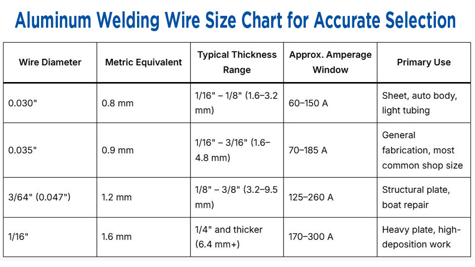
Core Aluminum Welding Wire Size Chart for MIG (GMAW)
Aluminum MIG operates almost exclusively in spray transfer with pure argon. Diameter selection starts with thickness and is refined by available machine output and feed-system capability.
Recommended Diameters by Base-Metal Thickness
| Wire Diameter | Metric Equivalent | Typical Thickness Range | Approx. Amperage Window | Primary Use |
|---|---|---|---|---|
| 0.030″ | 0.8 mm | 1/16″ – 1/8″ (1.6–3.2 mm) | 60–150 A | Sheet, auto body, light tubing |
| 0.035″ | 0.9 mm | 1/16″ – 3/16″ (1.6–4.8 mm) | 70–185 A | General fabrication, most common shop size |
| 3/64″ (0.047″) | 1.2 mm | 1/8″ – 3/8″ (3.2–9.5 mm) | 125–260 A | Structural plate, boat repair |
| 1/16″ | 1.6 mm | 1/4″ and thicker (6.4 mm+) | 170–300 A | Heavy plate, high-deposition work |
These ranges assume DCEP, 100 % argon, and flat or horizontal position. Vertical or overhead work normally drops 10–15 % on both amperage and wire-feed speed.
Starting Parameters Linked to Each Diameter
For 0.030″ wire on 1/8″ plate a practical starting point is 110–140 A at 20–24 V and 300–450 ipm wire speed. The same thickness with 0.035″ wire moves to 120–160 A, slightly lower wire-feed speed, and comparable voltage.
On 1/4″ material, 3/64″ wire typically runs 180–230 A at 24–27 V while 1/16″ wire on thicker sections climbs toward 250–300 A. Always verify contact-tip size matches the wire diameter exactly; a mismatched tip accelerates burn-back and tip wear.
Alloy Selection That Overrides Simple Diameter Rules
Diameter alone does not guarantee joint performance. Filler chemistry must match base-metal series and service requirements.
ER4043 Versus ER5356 Decision Points
ER4043 (approximately 5 % silicon) offers lower melting temperature, higher fluidity, and superior crack resistance on 6xxx-series alloys such as 6061 and 6063. It produces smoother, brighter beads and is preferred when appearance after anodizing or minimal distortion matters. Tensile strength of the deposited metal is lower—typically around 28–30 ksi.
ER5356 (approximately 5 % magnesium) delivers higher as-welded strength (approximately 38 ksi), better ductility, and superior corrosion resistance in marine or salt-exposed environments. It is the standard choice for 5xxx-series alloys (5052, 5083, 5086) and for welding 6xxx to 5xxx combinations.
Feedability is generally better than 4043 because the wire is slightly stiffer, yet the arc is less fluid and can produce more black smut.
When both strength and crack resistance are required, 5356 is usually selected for structural members while 4043 is retained for thin-gauge or cosmetic work. Elevated-temperature service above roughly 150 °F often favors 4043 to avoid magnesium-related embrittlement.
Thickness-Driven Alloy and Diameter Combinations
On 1/16″–1/8″ 6061 sheet the combination of 0.030″ or 0.035″ ER4043 keeps heat input low enough to limit distortion. The same thickness in 5083 marine plate switches to 0.035″ ER5356 to maintain strength and corrosion performance.
For 3/8″ 6061 plate, 3/64″ ER4043 or ER5356 both work; the choice then depends on whether the joint will be anodized (favor 4043) or must carry higher shear loads (favor 5356).
Feed-System Constraints That Dictate Practical Wire Size
Aluminum wire is soft and buckles easily. Diameter selection is therefore limited by the feeding hardware as much as by metallurgy.
Spool-Gun and Push-Pull Requirements
Most constant-voltage power sources require a spool gun or push-pull torch for reliable aluminum feeding beyond a few feet of liner. Spool guns commonly support 0.030″–0.035″ on lighter units and up to 1/16″ on heavier 200 A+ models.
Attempting to push 0.030″ wire more than 10–12 ft through a standard steel liner produces frequent bird-nesting. Larger diameters (3/64″ and 1/16″) generate higher column strength and feed more reliably, which is why many production shops standardize on 3/64″ once material thickness allows it.
Drive-Roll and Contact-Tip Matching
U-groove drive rolls sized exactly to the wire diameter, polished and set to light tension, prevent shaving. Contact tips must be aluminum-specific and one size larger than the steel equivalent in some systems to accommodate thermal expansion. A 0.035″ aluminum tip is commonly used with 0.035″ wire; running 0.030″ wire through a 0.035″ tip increases burn-back frequency.
Heat-Input and Transfer-Mode Effects of Wire Diameter
Current density (amperes per square millimeter of wire cross-section) governs penetration profile. Smaller diameters raise current density and produce deeper, narrower penetration at a given amperage. Larger diameters spread the same current over greater area, lowering density and widening the bead.
Spray-Transfer Thresholds by Diameter
Spray transfer on aluminum typically begins near 150 A for 0.030″ wire, 165 A for 0.035″, and 220 A for 0.045″/3/64″. Below these thresholds the process drops into globular or unstable short-circuit modes that produce excessive spatter and incomplete fusion.
Therefore a machine limited to 180 A output is best paired with 0.030″ or 0.035″ wire; higher-output machines can exploit 3/64″ or 1/16″ for faster travel speeds and higher deposition rates on thick plate.
Multi-Pass Considerations on Heavy Section
When plate thickness exceeds the single-pass capability of the chosen diameter, root passes are often run with a smaller wire for better control, then fill and cap passes switch to a larger diameter for deposition efficiency.
On ½” plate, a 0.035″ root followed by 3/64″ or 1/16″ fill layers is a common sequence that balances fusion and productivity.
Shielding-Gas and Joint-Design Interactions with Wire Size
Pure argon is the baseline for all common aluminum wire diameters. Helium additions (25–75 %) raise arc energy and are sometimes introduced on sections thicker than ⅜” or when deeper penetration is required without increasing wire diameter.
Gas flow rates scale roughly with diameter: 25–30 cfh for 0.030″, 30–40 cfh for 0.035″, and 40–55 cfh for 3/64″–1/16″ under typical draft-free conditions.
Joint design further modifies effective heat input. A tight square butt on thin sheet favors the smallest practical diameter to limit melt-through. An open V-groove on thicker plate accepts larger wire because the added volume of filler compensates for the higher deposition rate.
Practical Selection Sequence for Shop Use
Measure base-metal thickness at the joint. Identify the alloy series and any post-weld requirements (strength, corrosion, anodize color).
Select the smallest diameter that still provides adequate deposition rate and stays above the spray-transfer threshold of the available machine. Confirm the feed system (spool gun or push-pull) and contact-tip inventory support that diameter.
Run a short test bead on scrap of identical thickness and alloy, then adjust voltage and wire-feed speed in small increments until the puddle is fluid, the toes wet cleanly, and the arc remains in stable spray. Record the final parameters for future identical joints.
Wrapping Up
Correct diameter selection keeps aluminum welds inside the narrow process window required for sound fusion, minimal distortion, and reliable mechanical properties. On production work the same decision also determines whether the feed system stays reliable for an entire shift or requires constant intervention.
Advanced operators further refine the choice by matching current density to joint restraint and by deliberately pairing a smaller-diameter root pass with a larger-diameter fill sequence on multi-pass heavy plate, preserving both penetration control and overall deposition efficiency.
FQAs
What aluminum wire size for 1/8 inch plate?
0.030″ or 0.035″ is the practical range. Start with 0.035″ at 120–150 A and 100 % argon if the machine and spool gun support it.
0.030 vs 0.035 aluminum wire – which is better?
0.030″ suits thinner material and lower-output machines; 0.035″ offers better feed reliability and covers a wider thickness range for most general fabrication.
Can I use 0.045 aluminum wire on thin material?
Only with careful heat control and higher travel speed. It is better reserved for 1/8″ and thicker to avoid burn-through and excessive reinforcement.
What size aluminum TIG filler rod matches MIG wire charts?
TIG filler rods follow similar thickness logic but are selected independently: 1/16″ rod for up to 1/8″ plate, 3/32″ for 1/8″–1/4″, and 1/8″ for thicker sections.


