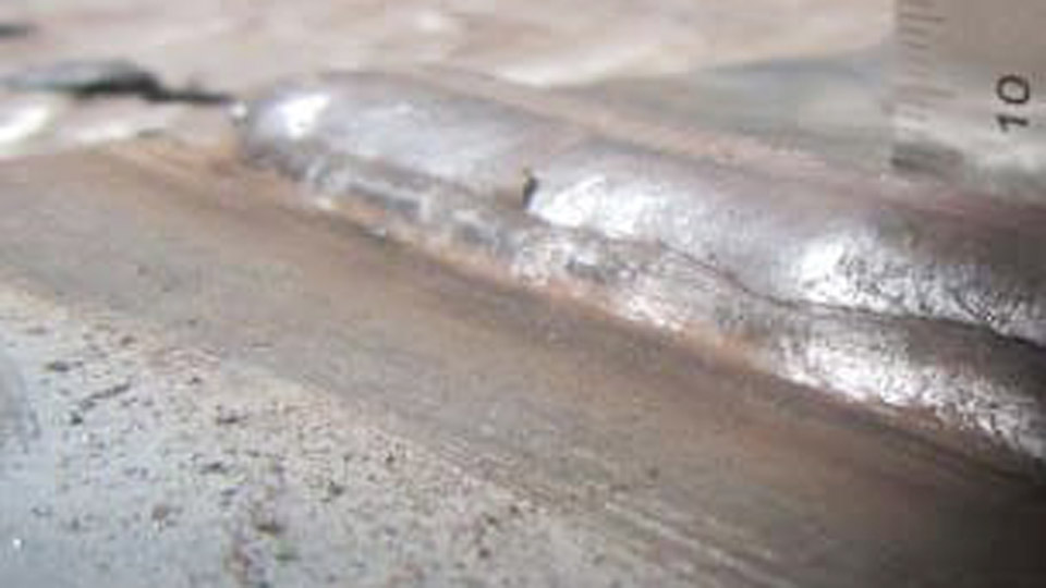
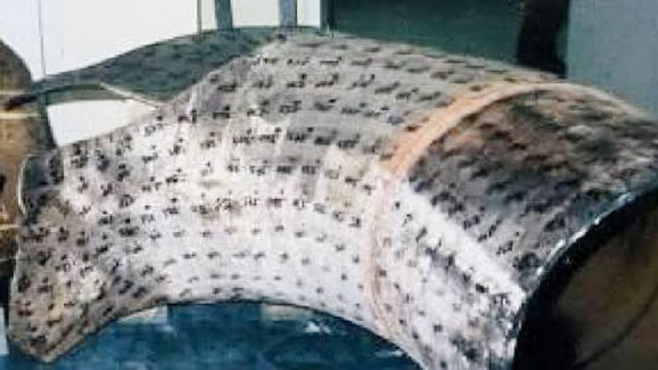
A completed fillet or groove weld looks solid until the slag is chipped and the surface shows pinholes, a sharp groove along the toe, or a cold lap that fails the first bend test. These are among the common welding defects and how to fix them that reject work under AWS D1.1, ISO 5817, or any structural code.
Defects reduce load-carrying cross-section, create stress concentrations, and initiate fatigue or brittle fracture.
Identifying the exact discontinuity type, its root cause (heat input, contamination, technique, or consumable condition), and the correct repair path determines whether the joint can be salvaged or must be cut out.
The decisions below focus on measurable parameters and process-specific actions that restore sound metal without introducing new discontinuities.
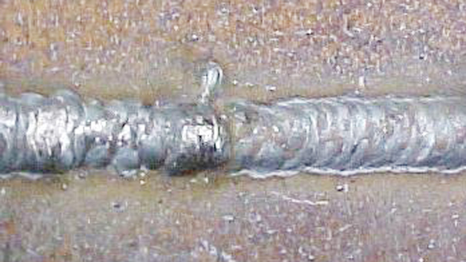
Image by rskr.irimee.in
Why Does Porosity Form and How Is It Removed?
Porosity appears as scattered, clustered, or linear gas cavities left when dissolved gases cannot escape the solidifying weld pool. It is volumetric and often acceptable in limited amounts under code tables, yet dense or linear porosity reduces fatigue life and can mask more serious planar defects.
Gas Sources That Differ by Process
In SMAW the primary sources are moisture in the electrode coating (especially low-hydrogen types left outside a rod oven), oil or rust on the joint faces, and excessive arc length that allows atmospheric nitrogen and oxygen to enter.
In GMAW and GTAW the dominant causes shift to inadequate shielding-gas coverage—flow rates below 15–20 CFH, leaks in hoses or fittings, drafts, or excessive stick-out that lets air entrain into the gas stream.
Galvanized coatings and primers release zinc or hydrocarbon vapors that produce wormhole porosity regardless of process.
Cleaning and Parameter Adjustments That Stop Gas Entrapment
Grind or wire-brush to bright metal at least 25 mm beyond the joint edges. Solvent wipe removes residual oils that grinding alone leaves. For SMAW, store E7018-type electrodes at 250–300 °F and limit out-of-oven exposure to the manufacturer’s stated hours. Shorten arc length to roughly the core-wire diameter.
For GMAW set shielding-gas flow at 20–25 CFH indoors (slightly higher outdoors with wind barriers) and keep contact-tip-to-work distance within 10–15 mm. Increase travel speed only after heat input is confirmed adequate; too-fast travel freezes the pool before gases escape.
Repair Sequence When Porosity Is Already Present
Map the distribution visually after slag removal. Surface pinholes may be accepted if size and spacing meet the applicable code table. Clustered or linear porosity requires excavation by grinding or arc-gouging to sound metal, extending 25 mm past the last visible pore.
Re-clean, correct the original cause (dry rods, verified gas flow, clean joint), then reweld with the same or a lower-heat procedure to avoid reintroducing gas. Confirm the repair with visual inspection plus PT or MT when the code demands it.
What Produces Undercut and When Must It Be Ground Out?
Undercut is a continuous or intermittent groove melted into the base metal at the weld toe or root and left unfilled. It reduces section thickness and acts as a sharp stress riser, particularly under cyclic loading.
Heat-Input and Travel-Speed Relationship
Excessive current or voltage melts the toe faster than filler metal can fill it. Travel speed that is too high leaves the same groove because the puddle does not dwell long enough to wet the edges.
On 1/8-inch E7018, currents above the upper third of the recommended range (typically >140–150 A in flat position) combined with fast travel commonly produce continuous undercut. The same electrode at 110–125 A with a brief pause at each toe during a controlled weave fills the groove completely.
Electrode or Gun Angle Effects on Toe Melting
A work angle that directs more than roughly 70 % of the arc force toward one plate edge concentrates heat and melts that edge preferentially. For fillet welds a 45° work angle with a slight drag (5–15°) balances heat. In groove welds an electrode angle that fails to reach both sidewalls leaves inter-run undercut that later traps slag.
Code Limits Versus Structural Rejection
AWS D1.1 and similar codes allow shallow undercut under static loading when depth stays within tabulated limits (often 1 mm or less depending on thickness and loading). Any undercut that exceeds the limit, or any undercut on cyclically loaded members, requires removal.
Grind the groove smooth, restoring the original plate contour, then deposit a small-stringer repair bead at reduced amperage. Blend the repair flush so no new stress concentration remains.
How Do You Recognize and Correct Lack of Fusion or Incomplete Penetration?
Lack of fusion (incomplete fusion) is a planar discontinuity where weld metal fails to bond to the base metal or to a previous pass. Incomplete joint penetration leaves an unfused root in a groove weld. Both behave like cracks under load and are almost always rejected.
Heat-Input and Access Decisions That Produce Fusion
Insufficient amperage or voltage leaves the fusion faces unmelted. Excessive travel speed or an electrode diameter too large for the root opening prevents the arc from reaching the root face. In SMAW a 1/8-inch electrode on a tight root gap often bridges rather than penetrates; switching to 3/32-inch or increasing root opening restores access.
In GMAW, short-circuit transfer at low voltage on thick plate frequently produces lack of sidewall fusion; raising wire-feed speed and voltage into spray or pulsed modes increases heat input and fusion.
Joint Preparation Variables That Control Root Access
Root face thickness, included angle, and root gap must match the process and electrode size. A root face thicker than 1.5–2 mm with insufficient current leaves incomplete penetration. B
ack-gouging depth and profile on double-sided joints must expose clean metal; a shallow or irregular back-gouge is a frequent cause of mid-thickness lack of fusion.
Repair Path for Planar Fusion Defects
These discontinuities cannot be left in place under most codes. Remove by grinding or gouging until bright, fused metal is reached on all faces. Re-prepare the joint to the original WPS geometry, verify fit-up, and reweld with parameters that guarantee fusion—higher heat input, correct angle, and confirmed interpass cleaning. Ultrasonic or radiographic examination is typically required after repair on critical joints.
Why Slag Inclusions Form and What Cleaning Standard Prevents Them
Slag inclusions are non-metallic flux residues trapped inside the weld metal or at fusion boundaries. They are most common in SMAW, FCAW, and SAW and act as crack starters when aligned.
Technique and Geometry Factors That Trap Slag
Slag runs ahead of the arc when the electrode angle is too steep or travel is too slow. Narrow groove angles or previous-pass undercut create pockets that hold slag. Incomplete removal between passes leaves islands of solidified flux that the next bead covers.
Interpass Cleaning Requirements That Eliminate Trapping
Chip and wire-brush every pass until the surface is free of visible slag and the undercut grooves are clean. Needle scalers reach tight corners. Any remaining slag must be ground out before the next layer. Maintain a slight drag angle so the arc force keeps molten slag behind the puddle rather than allowing it to flow forward.
When Inclusions Require Full Excavation
Scattered small inclusions may meet volumetric acceptance limits. Linear or aligned slag that approaches planar character is treated as a rejectable discontinuity. Excavate to sound metal, re-clean, and reweld. Confirm with radiography or ultrasonic testing when the original inspection method detected the inclusion.
How Do Hot Cracks Differ from Hydrogen-Induced Cracks and What Stops Each?
Cracks are planar discontinuities with sharp tips and zero acceptance under virtually every welding code. Hot cracks form during solidification; cold (hydrogen-induced) cracks appear hours or days later.
Solidification Cracking Mechanisms and Bead-Shape Control
Hot cracks follow the centerline of a weld bead that solidifies with a high depth-to-width ratio or high restraint. Sulfur or phosphorus segregation worsens the problem.
Reduce heat input, widen the bead with a controlled weave or multiple stringers, and select filler metals with low residual elements. Avoid crater cracks by back-filling the termination crater or using current down-slope.
Hydrogen Sources and Delayed Cracking Prevention
Moisture in consumables, surface contaminants, and humid atmospheres introduce diffusible hydrogen. Combined with a hardenable HAZ microstructure and residual stress, hydrogen produces under-bead or toe cracks.
Use low-hydrogen electrodes stored and handled per manufacturer limits, preheat thick or high-carbon steels to the temperature required by the WPS, and maintain interpass temperature. Post-weld heat treatment or controlled cooling further reduces risk on restrained joints.
Immediate Actions When Cracks Are Found
Any crack requires complete removal. Grind or gouge beyond the crack tips, verify with magnetic-particle or penetrant inspection that the crack is gone, then reweld under corrected conditions (preheat, low-hydrogen consumables, lower restraint if possible). Never attempt to “weld over” a crack.
Spatter, Overlap, and Burn-Through: Parameter Decisions That Control Surface Defects
Spatter consists of droplets expelled from the arc that adhere to the base metal. Overlap is weld metal that rolls over the toe without fusing. Burn-through is complete melting through the root or thin plate.
Current and Arc-Length Settings That Limit Spatter
Excessive current, long arc length, and wrong polarity increase spatter. In SMAW keep arc length short and stay inside the electrode’s recommended range. In GMAW, correct voltage for the chosen transfer mode and clean contact tips reduce droplet expulsion. Anti-spatter compounds help cleanup but do not fix the parameter root cause.
Travel Speed and Filler Volume That Prevent Overlap
Too-slow travel or excess filler deposition causes molten metal to over-run the unmelted toe. Increase travel speed or reduce wire-feed speed / electrode size until the puddle wets and fuses rather than rolls over. Overlap is a form of incomplete fusion and must be ground flush.
Heat-Input Limits That Avoid Burn-Through
On thin sheet or wide root gaps, reduce amperage, increase travel speed, or use a backing bar / copper chill. Pulsed GMAW or smaller-diameter electrodes give finer heat control. Once a hole forms, the repair requires bridging with reduced heat and often a temporary backing.
Wrapping Up
Defect identification begins with visual examination after cleaning, followed by the appropriate NDT method when the discontinuity may be subsurface. Each defect maps to a specific combination of heat input, cleanliness, joint geometry, and technique.
Correct the root cause before repair; otherwise the same discontinuity reappears. Advanced operators treat every rejected weld as process data: record the exact parameters, consumable lot, and joint fit-up that produced the defect, then adjust the WPS or welder technique so the next joint meets acceptance criteria on the first pass.
FAQs
What causes porosity in stick welding?
Moisture in low-hydrogen electrodes, contaminated base metal, or excessive arc length. Store rods in a heated oven, clean to bright metal, and keep arc length equal to electrode diameter.
How do you fix undercut on a weld?
Grind the groove smooth to restore plate contour, then deposit a small stringer bead at reduced amperage. Severe undercut that exceeds code depth limits must be fully removed and rewelded.
Is lack of fusion repairable?
Yes, but only by complete excavation to sound metal, re-preparation of the joint, and rewelding with parameters that ensure fusion. Planar lack of fusion is not acceptable under structural codes.
What is the difference between hot cracks and cold cracks?
Hot cracks form during solidification from chemistry or bead shape; cold cracks appear later from hydrogen, hardenable microstructures, and residual stress. Prevention methods differ: bead-shape control versus low-hydrogen practice and preheat.