
Unbalanced settings produce immediate weld defects: a ropey convex bead from insufficient voltage relative to wire feed speed, lack of fusion from excessive travel speed, or deep undercut and porosity when shielding gas and amperage fight each other.
Understanding how amperage, WFS, voltage, travel speed, and shielding gas affect welding is the difference between a procedure that consistently meets code and one that generates rework. These five variables interact continuously in GMAW (MIG).
Changing one forces compensatory adjustments in the others to maintain heat input, metal transfer mode, and bead geometry. Operators who treat them as independent dials spend more time grinding than welding.
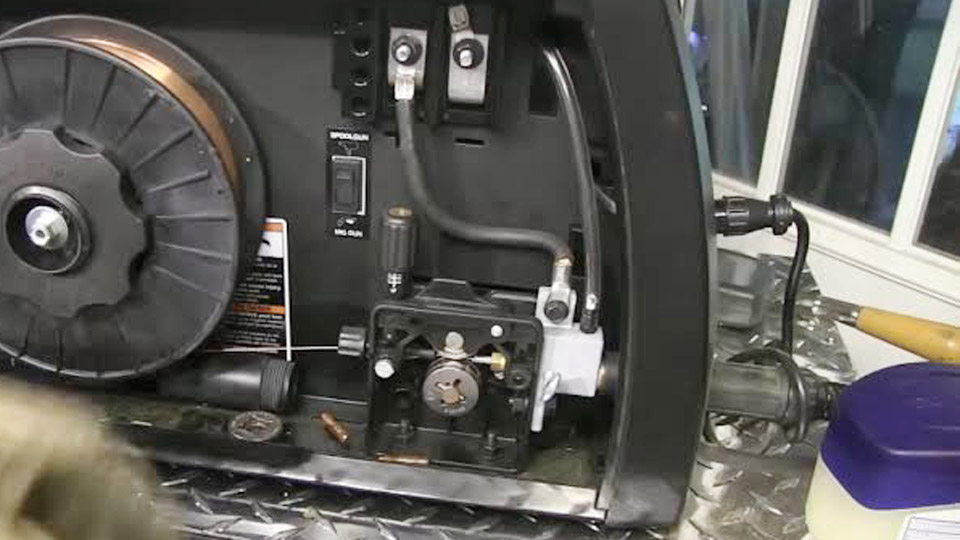
Image by testtalkhq
What Happens When Amperage Changes in Relation to the Other Variables
Amperage is the primary driver of penetration and deposition rate. In constant-voltage MIG machines the operator does not set amperage directly; the machine supplies whatever current is required to melt the wire at the selected feed rate.
How Amperage Controls Penetration Depth
Higher amperage increases the depth of fusion into the base metal. For mild steel with 0.035-inch solid wire, moving from 120 A to 180 A can shift a fillet from partial to full penetration on ¼-inch plate when voltage and travel speed remain constant.
Excessively high amperage, especially with metal-cored wire, produces a dull, flaky surface and can overheat the joint enough to cause distortion or burn-through on thinner sections.
Interaction Between Amperage and Heat Input
Heat input is calculated as

Amperage and travel speed exert the strongest influence. Doubling amperage while holding voltage and speed constant doubles heat input. Procedures limited by maximum heat input (for example, certain structural or stainless applications) therefore require coordinated reductions in amperage or increases in travel speed.
How Wire Feed Speed Determines Amperage and Deposition
Wire feed speed is the operator’s primary control for current on a CV power source. Increasing WFS forces the power source to deliver more amperage so the additional wire can be melted at the same rate it is fed.
WFS Ranges That Produce Short-Circuit Versus Spray Transfer
For 0.035-inch ER70S-6 wire, short-circuit transfer typically occurs between 150–280 IPM (roughly 90–160 A). Spray transfer begins above approximately 350–400 IPM (200 A and higher) when argon-rich shielding gas and sufficient voltage are present. Crossing into globular transfer (large, irregular droplets) occurs in the intermediate band if voltage is too low or the gas mix is CO₂-heavy.
Adjusting Travel Speed When WFS Increases
As deposition rate rises with higher WFS, travel speed must also increase to keep the arc at the leading edge of the puddle and maintain the desired bead size. Failure to raise travel speed produces excessive reinforcement, a convex profile, and potential slag entrapment in multi-pass welds.
How Voltage Shapes Arc Length and Bead Geometry
Voltage primarily controls arc length and the width of the arc cone. It has a secondary effect on heat input but a dominant effect on bead shape and toe wetting.
Voltage Too Low Relative to WFS
When voltage is insufficient for the selected wire feed speed, the wire stubs into the workpiece. The arc becomes short and harsh, producing a narrow, high-crowned bead with poor fusion at the toes and increased spatter. Operators hear a sharp, irregular popping sound rather than a steady crackle or hiss.
Voltage Too High Relative to WFS
Excess voltage lengthens the arc, widens the cone, and flattens the bead. Undercut appears along the toes, spatter increases, and gas coverage can be disrupted, leading to porosity. On thin material the longer arc also raises the risk of burn-through because heat is distributed over a larger area.
Practical Voltage Windows for Common Wire Diameters
For 0.030-inch wire on ⅛-inch steel in short-circuit mode, 17–20 V is typical. For 0.045-inch wire in spray transfer on thicker plate, 26–30 V is common when paired with 90/10 or 98/2 argon mixes. Voltage must track WFS: a 50 IPM increase in feed speed often requires a 1–2 V increase to keep the arc stable.
How Travel Speed Controls Heat Input and Bead Profile
Travel speed determines the time the arc spends on any given length of joint. It is the variable most operators adjust last, yet it exerts equal influence with amperage on final heat input.
Effects of Excessive Travel Speed
Moving too fast produces a narrow, undercut bead with incomplete fusion and a high, peaked profile. Penetration decreases because the heat source does not dwell long enough to melt the root or toes. On open-root joints the result is lack of penetration; on fillets the legs become unequal.
Effects of Insufficient Travel Speed
Slow travel increases heat input, widens the bead, and can cause excessive reinforcement or burn-through. The puddle grows large and fluid, making positional welding difficult and increasing the chance of undercut on the upper toe of a horizontal fillet.
Matching Travel Speed to Deposition Rate
A practical starting range for hand-held MIG on mild steel is 10–18 IPM for short-circuit transfer and 12–22 IPM for spray. When WFS is raised to increase deposition, travel speed must rise proportionally so that the finished weld size remains constant.
Many procedures specify a target heat-input range; operators calculate the required speed once amperage and voltage are locked.
How Shielding Gas Composition Changes Transfer Mode and Weld Properties
Shielding gas determines the possible metal-transfer modes, penetration profile, spatter level, and mechanical properties of the deposit.
Carbon Dioxide Versus Argon-Rich Blends
100 % CO₂ produces deep, finger-like penetration and a more oxidized surface but generates higher spatter and a coarser bead. It supports short-circuit and globular transfer only.
Adding argon (for example, 75 % Ar / 25 % CO₂) stabilizes the arc, reduces spatter, and allows both short-circuit and spray transfer.
Higher argon percentages (90/10 or 98/2) further clean the arc and enable true spray transfer at lower currents, but penetration becomes broader and shallower.
Gas Selection for Specific Transfer Modes
Short-circuit transfer works with C25 or 100 % CO₂. Spray transfer requires at least 80–85 % argon. Pulsed spray can operate with slightly lower argon content because the peak current assists droplet detachment. Flow rates of 25–40 CFH measured at the nozzle are typical; higher travel speeds or drafts require increased flow to maintain coverage.
Influence on Mechanical Properties
Argon-rich mixes generally produce higher tensile and yield strength with slightly lower ductility. Higher CO₂ content improves ductility and crack resistance at the expense of strength. For structural work governed by AWS D1.1, the gas mixture listed on the WPS must be followed exactly because it affects both transfer mode and deposited chemistry.
Decision Sequence for Balancing All Five Variables on the Shop Floor
Begin with material thickness and joint type to select approximate amperage (rule of thumb: 1 amp per 0.001 inch of thickness for mild steel).
Convert that amperage into WFS using wire-diameter multipliers (approximately 2 IPM per amp for 0.030-inch wire, 1.6 IPM per amp for 0.035-inch, 1 IPM per amp for 0.045-inch). Set voltage to produce a stable arc length for the chosen WFS and gas.
Finally adjust travel speed so the bead width and reinforcement match the joint requirements while keeping heat input within procedure limits. Verify on scrap of identical thickness and joint geometry; measure actual amperage with a clamp meter if the machine does not display it.
When the arc produces a consistent crackle (short-circuit) or smooth hiss (spray), the slag or oxide peels cleanly, and the toes blend without undercut or lack of fusion, the five variables are correctly balanced.
Advanced operators further refine results by holding contact-tip-to-work distance constant (⅜–½ inch short-circuit, ⅝–¾ inch spray) because stick-out changes effective amperage even at fixed WFS settings.
FAQs
What WFS should I use for 0.035 wire on 1/4-inch mild steel?
Start between 300–380 IPM with C25 gas and 20–23 V for short-circuit or low-spray transfer. Confirm actual amperage falls near 160–200 A and adjust travel speed to 12–16 IPM.
How does increasing voltage affect weld bead shape?
Higher voltage lengthens the arc, widens the bead, and flattens the crown. Too much voltage creates undercut and excess spatter; too little produces a narrow, convex bead with poor toe fusion.
Can I use 100 % CO₂ for spray transfer MIG?
No. Spray transfer requires an argon-rich mixture (typically ≥80–85 % argon). 100 % CO₂ supports only short-circuit or globular transfer and produces higher spatter.
How do I calculate heat input when adjusting travel speed?
Use the formula (60 × Amps × Volts) ÷ (1000 × Travel Speed in IPM). Raising travel speed lowers heat input proportionally and is the fastest way to stay under maximum heat-input limits without changing penetration.


