Building your own spot welder from an arc welder can be an affordable solution for joining thin sheet metal without investing in a dedicated resistance welding machine. However, learning how to make a spot welder from an arc welder involves more than attaching copper electrodes.
The transformer output, secondary wiring, electrode design, and current delivery must work together to produce enough heat at the contact point without overheating the equipment or damaging the workpiece. A poorly designed conversion can lead to inconsistent welds, excessive electrode wear, or electrical hazards.
When the modification is planned correctly, it can produce reliable spot welds for light fabrication, automotive sheet metal repairs, and hobby projects.
Understanding the core principles behind the conversion helps you build a safer, more effective tool while recognizing its practical limitations compared to a purpose-built spot welder.
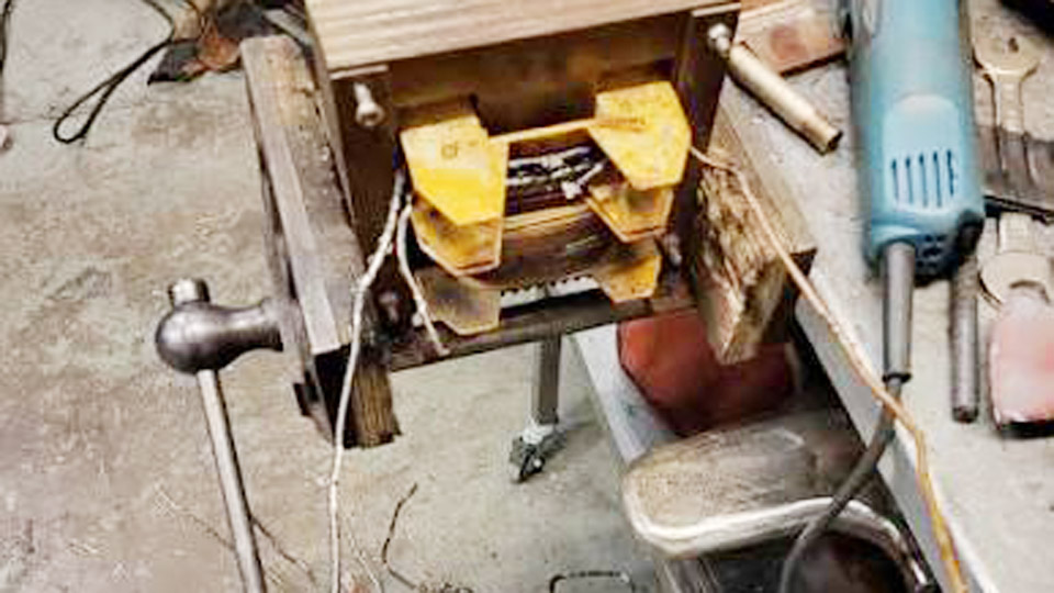
Image by mig-welding.co.uk
Which Arc Welders Work for Spot Welding Conversion
Transformer vs Inverter Machines
Transformer-type “buzz box” stick welders are the only practical candidates for a full secondary-winding conversion. These machines use a large iron core and high-current secondary windings that can be removed and replaced with a few turns of heavy copper cable.
The result is an open-circuit voltage of roughly 3–5 V and secondary currents in the 2,000–6,000 A range for short duty cycles.
Inverter-based MMA welders cannot be converted the same way. Their electronics are designed for constant-current arc control and typically shut down or limit output under a dead short. Using an inverter as a resistance power source usually yields only mild heating rather than a proper weld nugget.
For inverter owners the realistic path is an accessory-style carbon-arc or consumable-electrode gun rather than internal modification.
Minimum Power Requirements
A 140–200 A transformer welder provides a usable core size. Smaller 90–110 A units lack the magnetic mass and primary current capacity needed for consistent high-amp secondary output.
Larger industrial 250–400 A machines give more headroom and allow thicker secondary cable, but they are heavier and require more careful primary-side contactor control.
Two Practical Conversion Paths
Accessory Gun Method Without Internal Changes
Commercial or homemade spot-weld guns attach directly to the electrode holder or output terminals of any AC or DC stick welder. One popular design uses a single carbon or copper electrode held in a spring-loaded or trigger-actuated housing.
The ground clamp is attached to the bottom sheet. When the electrode contacts the top sheet under light pressure and the welder is energized, a brief arc melts the top panel into the lower one.
Typical operating range for 18–22 gauge mild steel is 40–60 A. Higher settings burn through; lower settings produce weak surface marks. Duty cycle is short—1–2 seconds of current followed by cooling.
This method requires no transformer work and preserves the original welder for normal stick welding. It works on both transformer and inverter machines.
Full Resistance Spot Welder Conversion
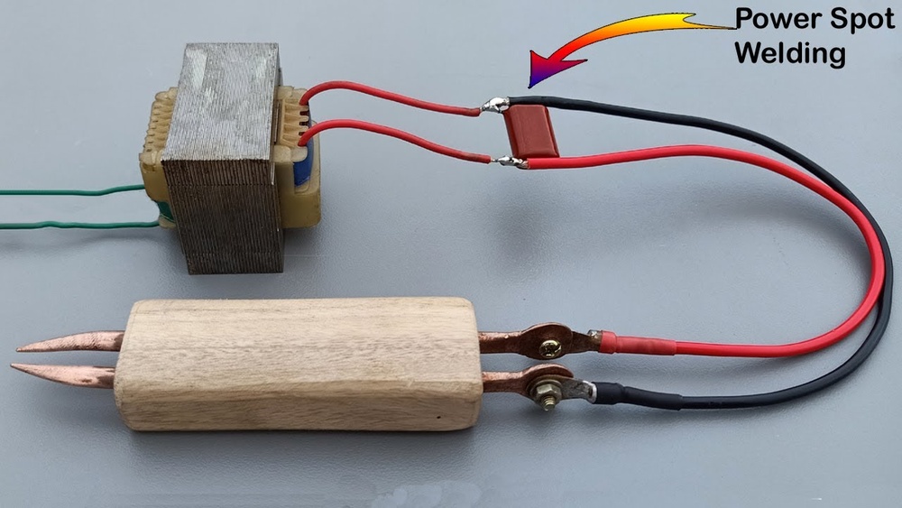
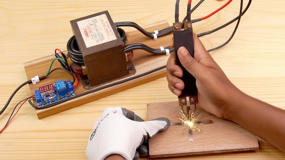
This path is limited to transformer welders. The secondary winding is cut out or ground free of the core. Two or three turns of heavy welding cable (70 mm² or larger, preferably copper) or solid copper bus bar are wound in its place.
Open-circuit voltage drops to 3–5 V while available short-circuit current rises dramatically. Copper electrode arms are then fabricated and mounted so that mechanical force can be applied through the electrodes while current flows.
The conversion permanently alters the machine for resistance welding only unless dual secondaries or a switchable setup is engineered. Expect several hours of careful work and the need for primary-side switching (contactor or solid-state relay) plus a timer for consistent weld time.
Building the Electrode Arms and Tips
Copper Selection and Tip Geometry
Electrodes must carry thousands of amperes with minimal resistance and must withstand repeated mechanical pressure. Hard-drawn copper or copper-chromium alloys (Class 2 or Class 3 resistance-welding copper) are preferred. Soft pure copper deforms quickly under force.
Tip diameter controls current density. For 0.8–1.2 mm sheet, a 5–7 mm flat or slightly domed tip is common. Smaller tips increase current density and risk electrode sticking or surface marking; larger tips spread the heat and may fail to form a proper nugget. Tips should be removable so they can be faced or replaced when mushroomed.
Mechanical Force and Alignment
Resistance spot welding requires simultaneous heat, pressure, and time. Electrode force for light sheet is typically 1.5–3.5 kN. Force can be applied by a foot pedal linked to a lever, a toggle clamp, or a small air cylinder. The arms must keep the electrode faces coaxial under load; misalignment produces edge welds or expulsion.
Insulate the arms from each other and from the frame with hardwood, phenolic, or high-temperature plastic blocks. Keep secondary cable runs as short and large in cross-section as possible to minimize voltage drop.
Controlling Current, Time, and Pressure
Primary-Side Switching
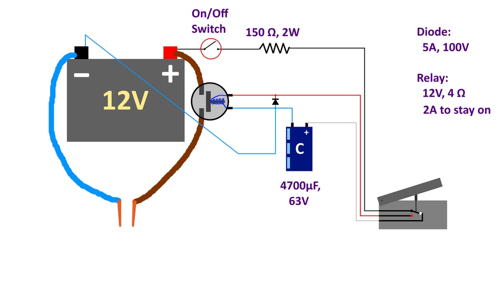
Because secondary currents are extreme, switching is done on the primary. A contactor or solid-state relay rated for the welder’s primary amperage is controlled by a foot switch or timer. Manual on/off with the welder’s own switch is possible but produces inconsistent weld times and higher risk of overheating.
Practical Weld Parameters for Mild Steel
For two sheets of 0.8 mm mild steel:
- Electrode force: approximately 2.0–2.5 kN
- Current: 7,000–9,500 A (depending on tip size and surface condition)
- Weld time: 6–12 cycles at 50/60 Hz (0.1–0.2 s)
- Hold time after current stops: 1–3 cycles to allow solidification under pressure
Thinner material needs less current and shorter time; thicker material requires higher force and longer time. Surface cleanliness is critical—scale, paint, or oil increases resistance and causes expulsion or weak bonds.
Duty Cycle and Cooling
Even with heavy cable, the transformer core and secondary heat rapidly. Limit continuous use to short bursts with cooling intervals. Some builders add forced-air cooling over the core or water-cool the secondary turns with copper tubing. Water cooling of the electrodes themselves is rare on DIY machines but useful for production runs.
Material Thickness Limits and Joint Design
Sheet Metal Capabilities
A well-executed conversion from a 140–200 A transformer reliably joins two layers up to about 1.5 mm mild steel. Beyond that the available current and force become marginal. Three layers or thicker stock usually require a larger industrial transformer or a commercial machine.
Galvanized or coated steels demand higher current or longer time because the coating increases contact resistance. Stainless steels work but need careful parameter adjustment to avoid carbide precipitation or excessive hardness in the nugget.
Lap Joint Considerations
Spot welds are almost always made in lap configuration. Edge distance should be at least 1.5–2 times the tip diameter to prevent edge breakage. Weld spacing depends on load requirements; closer spacing increases strength but also heat input and possible distortion.
Safety and Electrical Considerations Specific to Conversion
High secondary currents produce strong magnetic fields and can cause cables to jump under short-circuit conditions. Secure all connections with proper lugs and hardware. Primary-side wiring must retain the original thermal protection or add appropriate fusing.
The low secondary voltage is not shock-hazardous in the same way as arc voltage, but the heat and molten metal expulsion still require eye and hand protection.
Never operate a modified transformer without verifying insulation integrity between primary and secondary. A ground fault on the primary can energize the entire frame.
Testing and Tuning the Finished Machine
Begin with clean test coupons of known thickness. Apply force first, then current for a measured short interval, then hold force while the nugget solidifies. Peel the coupons apart to examine the nugget diameter and fracture mode. A good weld pulls a full button; interfacial failure indicates insufficient heat or force.
Adjust one variable at a time—current (via primary taps or series resistance if available), time, or force—until consistent buttons appear. Record the settings for each material thickness; they become the working reference.
Decision Guide: Accessory Gun or Full Conversion
Choose the accessory gun if:
- You own an inverter or need to keep the original stick function
- Work is limited to 18–22 gauge sheet
- Time and risk of permanent modification are concerns
Choose full conversion if:
- You have a surplus transformer welder
- You need higher current for thicker material or production rates
- You want true resistance welds without consumable electrodes
Both routes satisfy the core need—localized fusion without continuous beads—but the resistance conversion delivers stronger, more repeatable results when the machine and skill level support it.
Wrapping Up
The most advanced practical insight is that electrode force and weld time are more critical than raw amperage once the secondary is correctly designed.
Many DIY builds fail not from lack of current but from insufficient or uneven pressure and uncontrolled duration. Master those two variables and the converted arc welder becomes a reliable production tool rather than a novelty.
FAQs
Can you use an inverter stick welder for resistance spot welding?
No. Inverter electronics limit or shut down under dead-short conditions and cannot deliver the multi-thousand-ampere pulses required for proper resistance nuggets. Use an accessory carbon-arc or consumable-electrode gun instead.
What secondary voltage is ideal after conversion?
3–5 V open circuit is the practical range. Higher voltage increases the risk of arcing at the electrodes; lower voltage may not overcome contact resistance on imperfect surfaces.
How thick can mild steel be welded with a converted 140–200 A transformer?
Two layers up to approximately 1.5 mm under good conditions. Thicker material or multiple layers require a larger core and higher force.
Do the electrodes need water cooling?
For occasional DIY use, solid copper tips with air cooling of the transformer are sufficient. Continuous production benefits from water-cooled electrodes and secondary turns to maintain tip geometry and duty cycle.