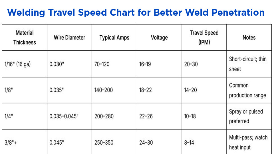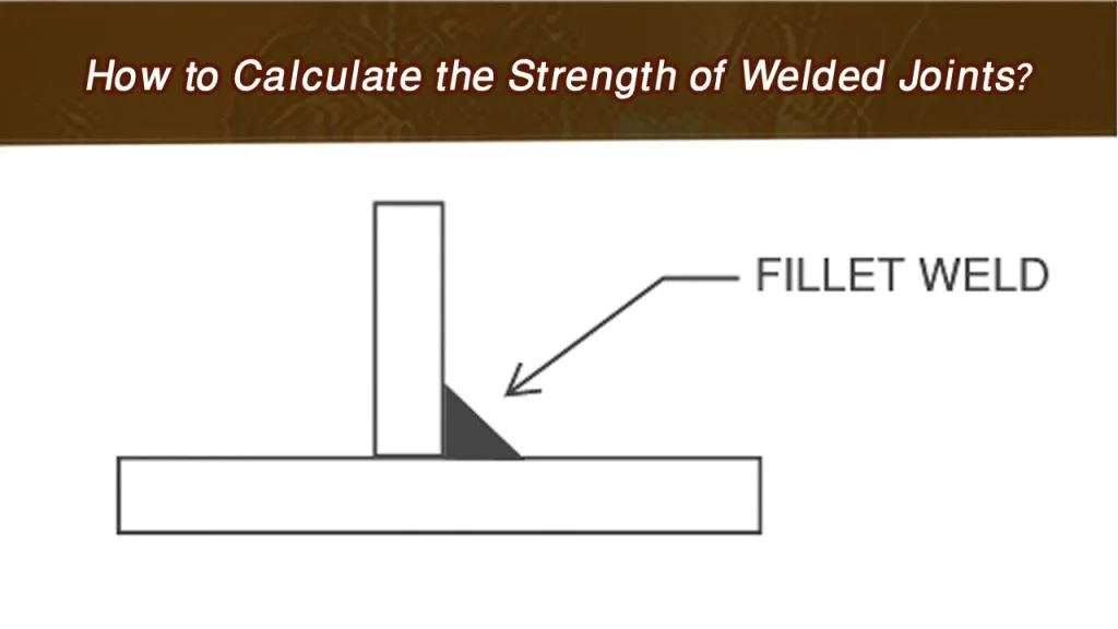
Choosing the wrong welding rod size or amperage can lead to poor penetration, excessive spatter, electrode sticking, and inconsistent weld quality. A reliable Welding Rod Size and Amperage Chart helps welders match electrode diameter with the correct current range based on material thickness and welding conditions.
Too little amperage makes it difficult to maintain a stable arc and achieve proper fusion, while excessive current can cause undercut, burn-through, and unnecessary distortion.
These problems are especially important when working with different electrode types, such as 6010, 6011, 6013, and 7018, because each has specific operating characteristics.
Understanding the relationship between rod diameter, amperage, and base metal thickness helps you select suitable settings before striking an arc. This makes it easier to produce consistent welds, reduce defects, and avoid costly rework.
Image by hobartbrothers
Core Amperage Ranges by Electrode Diameter and Classification
Manufacturer charts list overlapping but distinct windows for each AWS classification because coating chemistry changes how much current the rod can carry before the arc becomes unstable.
E6010 and E6011 Cellulosic Electrodes
These fast-freeze rods demand DCEP for deep penetration. Typical ranges:
3/32″ (2.4 mm) — 40–85 A
1/8″ (3.2 mm) — 75–135 A
5/32″ (4.0 mm) — 110–175 A
3/16″ (4.8 mm) — 140–215 A
E6011 adds AC capability and runs slightly lower on some machines. Use the lower half of the range for open-root pipe and vertical-up work; the upper half for flat plate where faster travel is possible.
E6013 Rutile Electrodes
Soft arc and easy slag release make these the default for light fabrication.
1/16″ (1.6 mm) — 20–40 A
3/32″ (2.4 mm) — 40–90 A
1/8″ (3.2 mm) — 80–130 A
5/32″ (4.0 mm) — 105–180 A
AC or DC either polarity works. Stay near the bottom of the band on sheet metal thinner than 1/8″ to avoid blow-through.
E7018 Low-Hydrogen Electrodes
Iron-powder coating raises the current requirement relative to cellulosic rods of the same diameter.
3/32″ (2.4 mm) — 70–110 A
1/8″ (3.2 mm) — 90–160 A
5/32″ (4.0 mm) — 130–210 A
3/16″ (4.8 mm) — 180–275 A
DCEP is preferred; AC requires a modest increase. Mid-range values (110–130 A for 1/8″) produce the quiet, fluid puddle expected on structural work.
E7014 and E7024 Iron-Powder Electrodes
Higher deposition rates shift the windows upward.
E7014 1/8″ — 110–160 A
E7014 5/32″ — 150–210 A
E7024 1/8″ — 140–190 A
E7024 5/32″ — 180–250 A
These rods are limited to flat and horizontal positions; vertical or overhead use is not recommended.
Matching Rod Diameter to Base-Metal Thickness
Diameter selection is driven by heat-sink capacity and joint access, not by a single fixed ratio.
Thin Material up to 1/8″
3/32″ or smaller electrodes keep heat input low enough to prevent burn-through. On 16-gauge to 1/8″ plate a 3/32″ E6013 at 50–70 A or a 3/32″ E7018 at 75–90 A produces controlled fusion without excessive distortion.
Medium Plate 1/8″ to 3/8″
1/8″ electrodes become the workhorse. A 1/8″ E7018 at 115–140 A handles single-pass fillets and multi-pass grooves on 1/4″ and 3/8″ material. The same diameter E6010 at 90–120 A is preferred when deep root penetration is required.
Heavy Plate 3/8″ and Above
5/32″ or 3/16″ rods raise deposition rate and reduce the number of passes. On 1/2″ plate a 5/32″ E7018 at 150–190 A fills a V-groove efficiently while still allowing interpass temperature control. Larger diameters (7/32″ and 1/4″) are reserved for high-production flat work where machine capacity and joint access permit.
How Welding Position Changes the Working Amperage
Gravity alters puddle support, so published ranges are adjusted in practice.
Flat and Horizontal Adjustments
Run the middle to upper third of the manufacturer window. Higher current increases travel speed and deposition without risk of the metal falling out of the joint. On a 1/8″ E7018 this typically means 125–145 A for flat fillets.
Vertical-Up and Overhead Reductions
Drop 10–15 % from the flat setting. The lower heat lets the slag and metal freeze faster, preventing drips and undercut. Vertical-up 1/8″ E7018 commonly settles at 105–120 A; overhead work stays in the same band or slightly higher to maintain arc force.
Polarity Selection and Its Effect on Heat Distribution
Polarity determines where two-thirds of the arc heat is concentrated.
DCEP (Electrode Positive) Preference
Most low-hydrogen and cellulosic rods run best on DCEP. Heat concentrates at the workpiece, producing deeper penetration and a more stable arc column. E7018 and E6010 data sheets list DCEP as the primary recommendation.
AC and DCEN Options
AC is required when only an AC machine is available; raise current 5–10 % to maintain arc stability. DCEN (electrode negative) is used with certain rutile and iron-powder rods when shallower penetration or higher deposition on thin material is desired. Always confirm the electrode package before switching polarity.
Practical Decision Process for Setting Final Amperage
Start at the midpoint of the chart range for the chosen diameter, polarity, and position. Strike a short test bead on scrap of identical thickness. Observe arc sound (quiet hiss for E7018, sharper crackle for E6010), puddle fluidity, and slag release. Adjust in 5 A increments. If the rod sticks or the bead piles high with incomplete fusion, raise current.
If undercut appears or the electrode tip overheats, lower current and increase travel speed. Record the final setting together with machine type, cable length, and ambient temperature for repeatability.
Correct rod size and amperage together determine whether a joint achieves full fusion and specified mechanical properties on the first pass. Once the chart value is locked in and confirmed by a test bead, further refinement comes from arc length and travel-speed control rather than continuous dial changes.
Advanced operators treat the published range as a starting envelope and then use stringer-bead technique plus interpass temperature limits to keep heat input inside code requirements on restrained or high-strength steel.
Wrapping Up
What amperage for 1/8″ 7018 rod?
90–160 A on DCEP. Most structural work starts at 120–130 A flat and drops to 110–120 A for vertical-up.
What size welding rod for 1/4″ steel?
1/8″ electrode is the standard choice. Pair it with 110–140 A for E7018 or 90–125 A for E6010/E6013 depending on required penetration.
How many amps for 3/32″ 6013?
40–90 A. Use the lower end (45–65 A) on thin sheet to avoid burn-through; the upper end on 3/16″ material.
Does amperage change for overhead welding?
Yes. Reduce 10–15 % from the flat setting so the puddle freezes quickly enough to stay in place without dripping.