Many welders assume a plasma welding machine is simply a higher-powered TIG unit or confuse it with plasma cutting equipment. That mix-up leads to poor joint selection, excessive heat input, or rejected parts when the process is applied outside its strength zone.
What is a plasma welding machine? It is a specialized arc-welding system that constricts a tungsten arc through a water-cooled copper nozzle, creating a high-velocity, high-temperature plasma jet capable of both melt-in and full-penetration keyhole welds.
The constriction raises energy density well above a conventional TIG arc, delivering narrower beads, deeper penetration at given current, and greater tolerance to torch-to-work distance.
Understanding the machine’s architecture, operating modes, and parameter windows determines whether the process solves a production problem or introduces unnecessary complexity and cost.
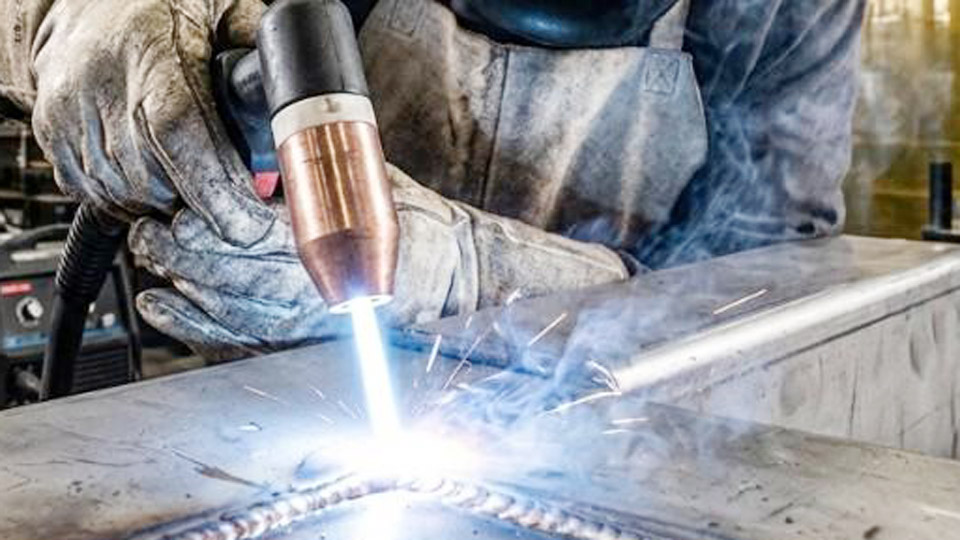
Image by ngen-global
How a Plasma Welding Machine Forms and Controls the Arc
The defining feature of any plasma welding machine is the recessed tungsten electrode inside a constricting nozzle. Plasma gas flows around the electrode tip and exits through a precisely sized orifice, forcing the arc into a columnar shape rather than the open, flared cone of TIG.
Pilot Arc Initiation and Transfer to the Workpiece
A low-current pilot arc is first established between the electrode and the copper nozzle. This ionizes the plasma gas (almost always argon) and creates a conductive path. When the torch approaches the workpiece, the main arc transfers from the nozzle to the work.
The pilot arc remains available for reliable restarts and allows stable operation at currents as low as 0.1 A. Transferred-arc operation is the standard welding mode; non-transferred arcs are reserved for heating or spraying applications.
Effect of Nozzle Bore and Electrode Setback
Bore diameter, electrode setback distance, and plasma-gas flow rate together control arc constriction. Smaller bores and greater setback produce higher energy density and greater arc force.
These variables must be matched to current level: an oversized bore at high current reduces constriction, while an undersized bore at low current risks nozzle damage. Water cooling of the nozzle is mandatory because the plasma column routinely exceeds 10,000 °C and can approach 28,000 °C.
Operating Modes That Dictate Penetration Profile and Travel Speed
Plasma welding machines operate across three overlapping current regimes, each producing a distinct weld geometry.
Microplasma Range for Foil and Precision Assemblies
Currents from 0.1 A to approximately 15 A generate a needle-like arc stable even at long standoff distances. This mode is used for bellows, thin-wall tubing, sensor housings, and foil as thin as 0.1 mm. Distortion remains minimal because total heat input is extremely low. Autogenous welding is the norm; filler addition is rare.
Medium-Current Melt-In Mode
Between roughly 15 A and 200 A the process behaves like a stiffened TIG arc. Penetration is deeper and the arc more tolerant of surface oxides than conventional GTAW at the same amperage.
Travel speeds are typically higher, and the heat-affected zone is narrower. This mode covers most manual and mechanized work on 1–6 mm material and can incorporate cold-wire or hot-wire filler.
Keyhole Mode for Single-Pass Full Penetration
Above approximately 100 A, with elevated plasma-gas flow and appropriate electrode setback, the plasma jet pierces completely through the joint thickness, forming a stable keyhole. Molten metal flows around the hole and solidifies behind the advancing torch, producing a full-penetration weld in one pass on square-butt joints.
Reliable single-pass keyhole welding is practical on stainless steel and titanium in the 2.5–8 mm range (occasionally up to 10–12 mm under optimized conditions). Keyhole welding is almost exclusively automated because torch height, travel speed, and gas flow must remain constant.
Essential Hardware Elements Inside a Plasma Welding System
A complete plasma welding machine comprises more than a power source and torch.
Torch Construction and Cooling Circuit
The torch houses the tungsten electrode (usually 2 % thoriated or lanthanated), the copper constricting nozzle, ceramic gas cups, and dual gas passages. Continuous water cooling protects the nozzle and electrode from the extreme thermal load.
Coolant flow rate and temperature must stay within manufacturer limits; insufficient cooling rapidly erodes the orifice and destabilizes the arc.
Dual-Gas Delivery and Flow Control
Plasma (orifice) gas is typically pure argon at low flow rates—often 0.5–5 L/min depending on mode. Shielding gas flows through the outer nozzle at higher rates (8–20 L/min) and may be argon, argon–hydrogen, or argon–helium blends according to base metal.
Separate mass-flow controllers or precision regulators are required; pressure fluctuations of only a few psi alter arc stiffness and keyhole stability.
Power-Source Characteristics
Most systems use a constant-current DC power source with drooping volt-ampere curve and open-circuit voltage of 70–90 V. Welding voltage typically settles between 20–35 V once the arc is established. Current ranges from microplasma levels up to 300–500 A on industrial machines.
Remote current control, pilot-arc circuitry, and gas-purge timers are standard. AC capability exists but is less common; most production work runs DC electrode negative.
Performance Contrasts with Conventional TIG That Influence Process Choice
The constricted arc changes several practical outcomes relative to GTAW.
Arc Stiffness and Torch-Height Tolerance
Because the plasma column is mechanically and thermally pinched, it remains columnar over a greater distance. Torch-to-work variation of several millimeters produces less change in bead shape than the same variation with TIG. This tolerance simplifies mechanized and robotic programming and reduces operator fatigue on long seams.
Heat-Affected Zone Width and Distortion Behavior
Higher energy density allows equivalent or greater penetration at higher travel speed and lower total heat input. Measured HAZ widths are frequently half those of TIG at comparable penetration. On thin stainless or titanium sheet this difference directly reduces residual stress and post-weld distortion.
Joint Preparation and Filler Requirements
Keyhole mode permits square-butt joints up to the single-pass thickness limit without beveling or filler. TIG on the same thickness normally requires a V-groove and multiple passes with filler. Melt-in plasma still benefits from tighter fit-up than most other processes but is more forgiving of minor gaps than laser welding.
Material Thickness Windows and Joint Configurations That Favor Plasma
Plasma welding machines deliver the greatest economic return inside defined thickness and joint envelopes.
Thin-Gauge and Autogenous Seams
Microplasma and low-medium current modes excel on 0.1–2 mm material where TIG risks burn-through or excessive distortion. Longitudinal tube seams, bellows, and medical-device components are common applications. Travel speeds of 200–600 mm/min are routine under mechanized control.
Intermediate Thickness Keyhole Capability
On 3–8 mm stainless, nickel alloys, and titanium, keyhole plasma frequently replaces multi-pass TIG or MIG. Square-butt preparation, single-pass full penetration, and minimal reinforcement reduce machining and filler cost. Aerospace ducting, chemical-process tubing, and food-grade vessels exploit this capability.
Limits Outside the Optimal Band
Below approximately 0.1 mm the process becomes unnecessary; above 10–12 mm multi-pass techniques or alternative processes (laser, electron beam, or submerged arc) usually prove more economical. Aluminum can be welded but requires special electrode polarity or AC systems and is less common than stainless or titanium applications.
Decision Criteria for Selecting a Plasma Welding Machine
Purchase or process-selection decisions rest on quantifiable factors rather than general claims of superiority.
Production Volume and Automation Readiness
High-volume longitudinal seams or repetitive precision parts justify the higher capital cost of a plasma system. The process integrates readily with CNC tables, orbital heads, and robotic cells. Low-volume or highly variable work rarely recovers the investment relative to skilled TIG.
Base-Metal and Code Requirements
Low-hydrogen, high-integrity joints on stainless, titanium, and nickel alloys benefit from the narrow HAZ and consistent penetration. When codes demand full-penetration single-pass welds without backing, keyhole plasma is often the practical solution. Carbon-steel structural work seldom requires the process.
Consumable and Operating-Cost Structure
Nozzles and electrodes are more expensive than TIG equivalents and must be replaced at defined intervals. Dual-gas consumption and water-cooler maintenance add ongoing cost. These expenses are offset only when travel-speed gains and reduced post-weld processing are realized.
Wrapping Up
Selecting the correct current regime, gas flows, and torch parameters for a given thickness and joint type determines whether a plasma welding machine delivers narrower beads, lower distortion, and higher productivity—or simply higher equipment complexity.
Operators who match mode and parameter sets to the actual metallurgy and production constraints extract the full technical advantage of the constricted arc while avoiding the common over-application that wastes capital and training time.
FAQs
Is a plasma welding machine the same as a TIG welder?
No. Plasma uses a constricted arc forced through a copper nozzle; TIG uses an open arc. The constriction raises energy density, enabling keyhole penetration and greater standoff tolerance that TIG cannot match.
What thickness can plasma welding handle in a single pass?
Reliable keyhole single-pass welds are common on stainless and titanium from roughly 2.5 mm to 8 mm. Optimized setups can reach 10–12 mm; beyond that multi-pass or alternative processes are preferred.
Does plasma welding require special gases?
Yes. A low-flow plasma (orifice) gas—almost always argon—and a separate higher-flow shielding gas are required. Argon–hydrogen or argon–helium blends are sometimes used for specific alloys.
Can plasma welding be done manually?
Medium-current melt-in mode can be performed manually, but keyhole mode is almost always automated because torch height, speed, and gas flow must remain constant for a stable keyhole.