Operators often struggle when a standard TIG arc fails to deliver consistent penetration on medium-thickness stainless or titanium while still producing excessive heat input and distortion.
How does plasma welding work differently to solve that exact problem? The process constricts the arc through a water-cooled copper nozzle, raising energy density far above an open TIG arc and enabling either controlled melt-in fusion or full-penetration keyhole welding in a single pass.
Understanding the torch geometry, gas circuits, and transfer sequence lets welders decide when plasma delivers measurable gains in speed, HAZ width, and joint preparation requirements versus conventional GTAW.
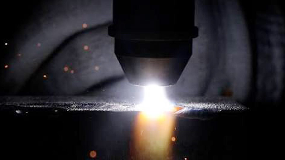
Image by ourcladding
What Creates the Constricted Plasma Arc Inside the Torch
The defining feature of plasma arc welding is the physical constriction of the arc column before it reaches the workpiece.
Role of the Recessed Electrode and Copper Nozzle
A non-consumable tungsten electrode sits inside a water-cooled copper nozzle rather than extending beyond the torch face as in TIG. Plasma gas flows through the annular space around the electrode and exits a precisely sized orifice at the nozzle tip.
The water-cooled copper wall forces the arc column to a smaller diameter, increasing current density, temperature (commonly 20,000–28,000 °C), and plasma velocity. Electrode setback—the distance the tip is recessed from the orifice—directly influences constriction severity.
Greater setback produces a stiffer, more columnar arc preferred for keyhole work; reduced setback softens the arc for melt-in applications.
Pilot Arc Initiation and Transfer to the Workpiece
Because the electrode never contacts the workpiece, a pilot arc must first be established between the electrode (negative) and the copper nozzle (positive). High-frequency or capacitor-discharge initiation ionizes the plasma gas at low current, typically 2–15 A.
Once the pilot arc stabilizes, the main welding current transfers to the workpiece, converting the circuit to transferred-arc mode. In transferred mode the workpiece becomes the anode, directing the majority of heat into the joint. Non-transferred mode keeps the arc between electrode and nozzle and is rarely used for welding metals.
Plasma Gas Versus Shielding Gas: Flow Rates and Selection Decisions
Two independent gas streams operate simultaneously; each serves a distinct function and must be balanced against current and orifice size.
Plasma (Orifice) Gas Requirements
Pure argon is the standard plasma gas because it ionizes readily and remains chemically inert. Flow rates are deliberately low—often 0.5–5 L/min for melt-in work and higher for keyhole—to avoid turbulence while still providing the mass flow needed for constriction.
Excess plasma gas flow increases arc force and can eject molten metal from the keyhole or accelerate nozzle erosion. Insufficient flow allows the arc to expand and lose its columnar shape.
Shielding Gas Composition and Flow
A separate outer gas cup supplies shielding gas that protects the molten pool and cooling weld metal from atmospheric contamination. Argon is common; argon–hydrogen mixtures (typically 2–5 % H₂) improve wetting and travel speed on stainless and nickel alloys; argon–helium blends raise heat input for aluminum or copper.
Shielding flow rates are substantially higher than plasma gas rates, commonly 10–20 L/min, and must remain laminar. The two gas streams never mix inside the torch; the plasma gas exits the orifice while shielding gas flows concentrically around it.
Melt-In Mode Versus Keyhole Mode: When Each Delivers Better Results
Operating mode is selected by the combination of current, plasma gas flow, and orifice diameter rather than by a simple switch.
Melt-In (Conduction) Mode Characteristics
At lower currents (typically under 100–150 A) and moderate plasma gas flow, the arc melts the surface without fully penetrating the plate. The resulting weld pool behaves similarly to a TIG pool but remains narrower and more stable because of the constricted energy distribution.
Microplasma (0.1–15 A) extends this regime to foil thicknesses where conventional TIG arcs become unstable. Melt-in mode is preferred for thin sections, cosmetic cover passes, and applications that require filler metal addition without risk of burn-through.
Keyhole Mode Penetration Mechanics
When current and plasma gas momentum rise sufficiently, the arc pressure displaces molten metal and opens a through-thickness cavity—the keyhole. Molten metal flows around the keyhole and solidifies behind the advancing torch, producing a full-penetration weld in a single pass on square-butt joints.
Typical thickness capability ranges from approximately 2.5 mm to 10–12 mm depending on alloy and travel speed. Keyhole stability depends on precise balance: too little plasma gas or current collapses the keyhole; excess force produces undercut or porosity at close-out.
Most production keyhole welding is mechanized because manual torch motion cannot maintain the required consistency.
Critical Operating Parameters That Control Penetration and Bead Shape
Four interdependent variables determine whether the arc produces the intended fusion profile.
Current, Orifice Diameter, and Gas Flow Interactions
Orifice diameter is matched to the intended current range. Smaller orifices (0.8–1.5 mm) concentrate the arc for keyhole or high-speed melt-in work; larger orifices reduce constriction and are used for softer melt-in beads or higher total current.
Current density inside the orifice rises rapidly as diameter decreases, so an undersized orifice at high amperage erodes quickly and can double-arc. Plasma gas flow must increase with current and decrease with larger orifice size to maintain the desired arc stiffness.
Travel Speed and Standoff Distance Limits
Keyhole travel speeds are typically two to three times those of equivalent TIG welds on the same thickness. Standoff (nozzle-to-work distance) is more forgiving than TIG arc length—often 3–6 mm is acceptable—because the plasma column remains collimated.
Excessive standoff still lengthens the arc column, drops energy density, and risks keyhole instability. Mechanized systems commonly incorporate arc-voltage control or fixed torch height to keep the relationship constant.
Equipment Requirements and Torch Cooling Demands
Plasma welding systems require a constant-current DC power source capable of both pilot-arc and main-arc output, a dedicated plasma console for gas metering and pilot-arc control, and a water-cooled torch. Torch cooling is non-negotiable; the copper nozzle absorbs intense radiant and conductive heat. Coolant flow rates of 1–2 L/min at sufficient pressure are typical.
Electrode grinding and concentricity must be maintained more carefully than in TIG because any eccentricity causes uneven orifice wear and arc wander. Most industrial plasma welding is performed with automated or robotic torch motion because the process window is narrower than manual TIG.
Materials and Joint Designs Where Plasma Outperforms TIG
Plasma arc welding shows clearest advantages on stainless steels, nickel alloys, titanium, and zirconium in the 2.5–10 mm thickness range when square-butt, single-pass full penetration is desired. Aerospace and medical tubing, thin-wall pressure vessels, and precision fabrications benefit from the reduced HAZ and lower overall heat input relative to multi-pass TIG.
Aluminum and copper can be welded but require helium-rich shielding and careful parameter control because of their high thermal conductivity. Joint fit-up must be tighter than for TIG; gaps larger than approximately 10 % of thickness destabilize the keyhole.
Autogenous welding is common in keyhole mode; filler is added only when metallurgical or reinforcement requirements demand it.
Wrapping Up
Selecting plasma over TIG is justified when single-pass penetration, higher travel speed, or reduced distortion outweigh the higher equipment cost and tighter process window. Microplasma fills the opposite niche—stable arcs at currents too low for reliable TIG.
In both regimes the recessed electrode and dual-gas architecture deliver the energy density that an open arc cannot match.
Advanced operators further stabilize keyhole close-out by programming a controlled current and plasma-gas ramp-down sequence, eliminating the porosity that uncontrolled termination frequently produces.