Wrong plasma cutter settings for aluminum produce immediate failures—heavy bottom dross that refuses to chip cleanly, wide oxidized kerfs that need extra grinding before welding, or incomplete cuts that stall mid-plate because heat dissipates too fast.
Aluminum’s high thermal conductivity and oxide layer demand different amperage, travel speed, torch height, and gas choices than mild steel of the same thickness. Matching these variables to the exact plate thickness and machine chart determines whether the edge is weld-ready or requires hours of cleanup.
Incorrect settings also shorten consumable life and risk warping thin sheet. Use manufacturer cut charts as the primary reference and treat the ranges below as practical starting points for common air-plasma systems.
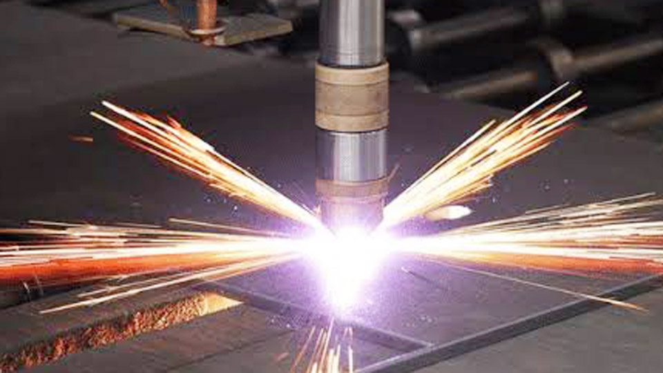
Image by resizeweld
Matching Amperage to Aluminum Thickness
Amperage supplies the energy density needed to overcome aluminum’s rapid heat dissipation. Most handheld and light industrial machines rate capacity higher on mild steel than on aluminum of equal thickness.
Thin Sheet Under 1/8 Inch
Run 25–45 A on 18-gauge to 1/8-inch material. Lower current reduces heat input and distortion risk while still maintaining a stable arc. Pair the lower end of the range with fine-cut nozzles when available. Higher amperage within this band increases speed but widens the kerf on very thin sheet.
Medium Plate 1/8 to 3/8 Inch
Most 40–60 A machines handle 1/8-inch aluminum cleanly at 40–50 A and 1/4-inch material at 50–70 A. At 3/8 inch, many 60–80 A units operate near the upper limit of their duty cycle. Exceeding the rated process current for the installed consumables accelerates nozzle and electrode wear without improving edge quality.
Thicker Plate and Machine Capacity Limits
For 1/2-inch and above, select a machine whose aluminum production-cut rating meets or exceeds the thickness. A 65–85 A system typically delivers quality cuts up to roughly 1/2 inch; 100 A+ systems extend reliable production cutting further.
Severance cuts on thicker plate remain possible at reduced speed but produce heavy dross and bevel that rarely meet fabrication standards.
Travel Speed Decisions That Control Dross and Distortion
Speed and amperage form a linked pair. Aluminum requires faster travel than mild steel of the same thickness at equivalent current to stay ahead of heat sink effects.
Recognizing Correct Spark Stream Angle
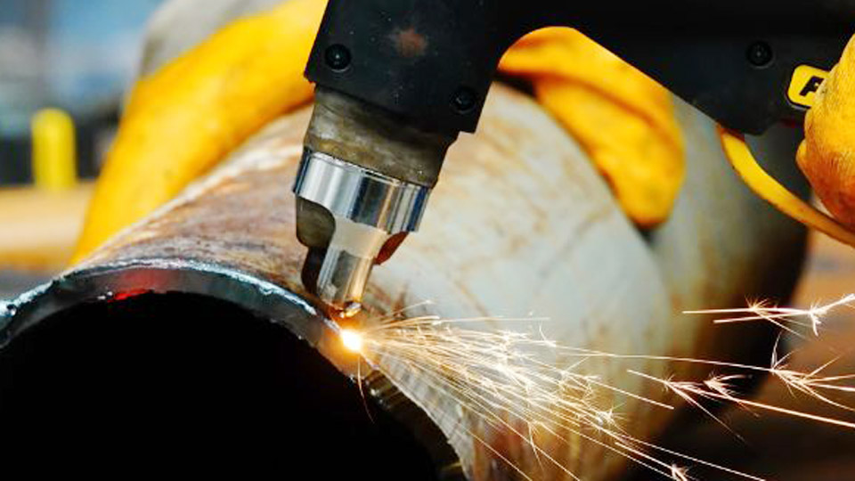
A trailing spark stream of 10–20 degrees from vertical indicates balanced speed. Sparks exiting straight down or backward signal excessive heat input and low-speed dross. Sparks spraying forward or failing to exit the bottom indicate travel that is too fast for the available energy.
Thickness-Specific Speed Windows
On a typical 45 A air process, expect best-quality speeds near 170 IPM on 1/8-inch aluminum and roughly 70 IPM on 1/4-inch plate. Production speeds run higher. On 60–80 A processes the same thicknesses support higher speeds while still maintaining edge quality.
Always start at the manufacturer’s best-quality speed and adjust in small increments while inspecting the bottom edge.
Speed Adjustments for Manual Versus Mechanized Cutting
Handheld operators often run slightly slower than chart values to maintain control. CNC or track systems can hold the higher production speeds listed in cut charts, reducing overall heat input per unit length and minimizing distortion on large panels.
Gas Selection and Pressure Requirements for Aluminum
Gas choice affects edge oxidation, dross adhesion, and weldability more than any other single variable after amperage and speed.
Compressed Air Performance and Limitations
Clean, dry, oil-free air at 65–90 PSI works for most non-critical cuts. It is economical and readily available. The resulting edge shows more oxide and may require light grinding or brushing before welding. Moisture or oil in the air supply produces porosity-like defects and rapid consumable wear.
Nitrogen for Cleaner Edges
Nitrogen as both plasma and shield gas reduces oxidation and yields a brighter, more weld-ready edge on thin to medium aluminum. Many dual-gas machines support this process.
Pressure ranges typically sit in the same 65–90 PSI band, but flow rates follow the specific process chart. Nitrogen costs more than air yet often saves finishing time.
Argon-Hydrogen Mixes on Thicker Material
For plate above roughly 3/8–1/2 inch where edge quality and penetration matter, H35 (35 % hydrogen / 65 % argon) plasma gas with nitrogen shield delivers higher energy density and smoother faces.
These processes require compatible torches and gas consoles and are more common on industrial systems than portable units.
Torch Height, Pierce Height, and Consumable Selection
Standoff distance shapes the arc and controls kerf angle and dross location.
Cut Height Versus Pierce Height
Cut heights for aluminum commonly fall between 0.06 and 0.125 inch depending on amperage and consumable set. Pierce height is set higher—often 150–200 % of cut height—to protect the nozzle from molten splash.
Pierce delay increases with thickness so the arc fully penetrates before travel begins. On thick plate many charts switch to edge starts to avoid piercing damage.
Matching Nozzle and Electrode to Process Current
Install the exact consumable set rated for the chosen amperage. Using a higher-current nozzle at reduced amperage or vice versa degrades arc constriction and edge quality. Fine-cut consumables improve thin-sheet results on some systems but are often restricted or not recommended for aluminum by certain manufacturers.
Drag Shields and Height Control
A drag shield or spring-loaded guide maintains consistent standoff on handheld cuts and protects the nozzle. On CNC tables, torch height control (THC) becomes essential for consistent results across uneven or warped plate.
Diagnosing Cut Quality Problems from Edge Appearance
Edge inspection provides the fastest feedback for parameter adjustment.
Low-Speed Dross Characteristics
Thick, hard, tenacious dross along the bottom edge indicates travel speed that is too slow relative to amperage. Increase speed 10–15 % and re-test. Excessive heat input also produces a rounded top edge and wider heat-affected zone.
High-Speed Dross and Incomplete Cuts
Fine, easy-to-remove dross or incomplete penetration with a jagged bottom edge signals travel that is too fast. Reduce speed or raise amperage within the consumable rating. Arc instability or flickering during the cut often points to low air pressure, worn consumables, or insufficient standoff.
Bevel and Kerf Width Issues
Excessive bevel on one side usually results from torch angle error or incorrect height. A kerf that is significantly wider than chart values indicates high amperage, low speed, or worn nozzle orifice. Measure kerf against the process chart and correct the dominant variable first.
Practical Decision Sequence for Setting Up a Cut
Begin with the machine’s published aluminum cut chart for the exact amperage, torch, and consumable combination installed. Select the row matching measured plate thickness. Set air or gas pressure while flowing, confirm dry supply, install matching consumables, and set cut and pierce heights.
Run a short test cut on scrap of identical alloy and thickness. Inspect both top and bottom edges, adjust speed first, then amperage or height only if needed. Record the final combination of amperage, speed, pressure, height, and consumable lot for future identical work.
This sequence accounts for machine calibration differences, ambient temperature, and alloy variations that generic tables cannot capture.
Correct plasma cutter settings for aluminum balance energy input against the metal’s rapid heat dissipation so the arc remains focused long enough to sever the plate cleanly without excess melting.
When the spark stream trails correctly, the bottom edge shows minimal dross, and the kerf matches chart width, the parameters are right for that thickness and machine.
Advanced operators further improve results by switching to nitrogen processes on parts destined for welding and by using edge starts or reduced pierce height on critical pierces to extend consumable life.
FAQS
What amperage for 1/4 inch aluminum plasma cutting?
Most 45–65 A machines start at 45–60 A for 1/4-inch aluminum. Confirm the exact value in the machine’s aluminum cut chart for the installed consumables and adjust speed to produce a 10–20 degree trailing spark stream.
Can I use the same plasma settings for aluminum as mild steel?
No. Aluminum usually needs higher travel speed and often different gas or slightly adjusted amperage because of its higher thermal conductivity. Always use the aluminum-specific row in the cut chart.
What air pressure for plasma cutting aluminum?
Typical range is 65–90 PSI of clean, dry, oil-free air while flowing. Check the process chart for the exact pressure and flow rate; moisture in the line causes rapid consumable wear and poor edge quality.
Why is there heavy dross on plasma-cut aluminum?
Heavy bottom dross most often results from travel speed that is too slow for the amperage and thickness. Increase speed first, verify dry air supply, and confirm torch height matches the chart before changing amperage.