An unstable, wandering arc or sudden tungsten inclusions in the puddle often trace back to one overlooked setup detail: incorrect electrode preparation. Learning how to grind tungsten for TIG welding correctly eliminates that variability by producing a symmetrical tip that focuses electron emission at a single, predictable point.
The grind direction, included angle, and final tip shape directly control arc column diameter, penetration profile, and electrode life under both DCEN and AC waveforms.
A radial grind or mismatched angle forces the arc to jump between micro-ridges, producing inconsistent bead width and higher risk of contamination. Proper longitudinal preparation restores arc stability and repeatable heat input across steel, stainless, aluminum, and exotic alloys.
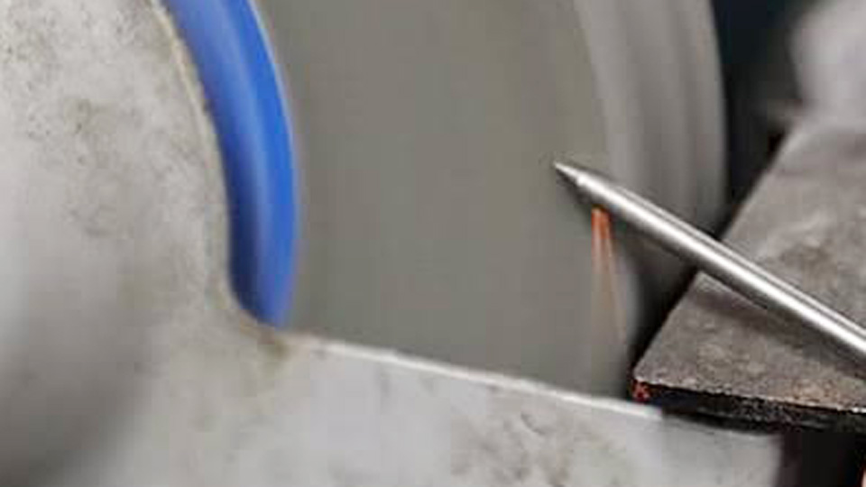
Photo by binzel-abicor
Why Longitudinal Grinding Direction Controls Arc Stability
Electrons travel more readily along continuous surface paths than across interrupted ridges. Tungsten electrodes are manufactured with the grain structure running lengthwise. Grinding across that grain (radial or circumferential) creates circular grooves that act as multiple competing emission sites.
Longitudinal Marks Channel Current to the Tip
When grind lines run parallel to the electrode axis, the current follows those lines straight to the extreme tip. The resulting arc starts cleanly, remains centered, and maintains a consistent cone shape. This longitudinal orientation is non-negotiable for DCEN work on steel and stainless and remains beneficial on modern inverter AC.
Radial Grinding Creates Arc Wander
Circumferential marks force electrons to jump from ridge to ridge. The arc begins off-center, spreads unpredictably, and often wanders around the tip circumference. On open-root pipe or orbital tube work the defect appears as uneven penetration and variable bead width that fails visual or radiographic inspection.
Surface Finish and Wheel Selection
Diamond or borazon wheels produce the cleanest longitudinal finish. Silicon-carbide bench wheels can leave embedded particles that later transfer into the weld. A dedicated wheel used only for tungsten prevents cross-contamination from steel or aluminum dust. Light, intermittent contact keeps the electrode below the temperature at which oxide dopants migrate and evaporate.
Selecting the Correct Included Angle for Material and Amperage
Included angle (the full cone angle) governs how tightly the arc focuses and how much heat the tip can tolerate before melting or eroding.
Narrow Angles (15°–25°) for Thin Material and Low Current
A long, sharp taper produces a wide, soft arc envelope with shallow penetration. These angles suit foil, thin-wall tube, and low-amperage sheet work where heat input must stay minimal. Taper length on a 3/32″ electrode commonly reaches 0.25–0.375″. The trade-off is faster tip erosion and higher risk of the point breaking off into the puddle if current rises.
Balanced Angles (30°–45°) for General Fabrication
Most hand TIG on plate and pipe settles in this range. A 30°–35° included angle gives moderate focus, reliable starts, and acceptable electrode life up to roughly 150–200 A on 3/32″ lanthanated or thoriated electrodes. On 1/8″ electrodes the same geometry handles higher current before the tip degrades. Taper length typically equals 2–2.5 times electrode diameter.
Blunt Angles (45°–60°+) for High Amperage and Thick Sections
Shorter tapers concentrate the arc into a narrow, high-energy column that drives deeper penetration. These geometries resist tip melt-back under high current and last longer on thick plate or heavy pipe. Arc starting becomes slightly more difficult and the bead profile narrows. Beyond 60° the arc can become unstable on some machines if stick-out or gas coverage is marginal.
| Included Angle | Typical Taper Length (3/32″) | Arc Character | Primary Use |
|---|---|---|---|
| 15°–20° | 0.30–0.375″ | Wide, soft | Thin sheet, foil, low amp |
| 30°–35° | 0.18–0.25″ | Balanced | General plate & pipe |
| 45°–60° | 0.08–0.15″ | Narrow, intense | Thick section, high amp |
Pointed, Truncated, or Balled: Matching Tip Geometry to Process
Tip shape interacts with polarity and waveform more than any other single preparation variable.
Pointed Tips for DCEN Steel and Stainless
A sharp point concentrates emission for precise puddle control and deep, narrow penetration. Keep a very small flat (0.005–0.015″) even on “sharp” tips when current exceeds 100 A; a pure needle can shed particles into the weld. Lanthanated, ceriated, and thoriated electrodes all respond well to this geometry under DCEN.
Truncated Tips for Higher Current and Inverter AC
After forming the desired taper, grind a deliberate flat of 0.010–0.030″ (roughly 10–20 % of electrode diameter). The flat resists melt-back, reduces tungsten transfer risk, and still maintains a focused arc. Modern inverter machines running AC aluminum often perform better with a truncated lanthanated tip than with a fully balled pure-tungsten electrode. The flat also improves arc starting consistency across polarity reversals.
Balled Tips for Traditional AC Aluminum
Pure (green) and zirconiated electrodes form a hemispherical ball under sufficient electrode-positive time. The ball diameter should stay below 1.5 times electrode diameter; larger spheres destabilize the arc and can drop into the puddle. On transformer machines this geometry remains standard. On advanced inverters many operators now prefer a truncated point and adjust AC balance and frequency instead of relying on a large ball.
Tools and Execution for Consistent Electrode Preparation
Consistency of geometry matters more than absolute perfection of any single tip.
Dedicated Grinder Versus Bench Wheel
A purpose-built tungsten grinder with adjustable angle stops and a collet produces repeatable results far faster than freehand work. When only a bench grinder is available, mount a diamond wheel and use a simple angle guide or fixture. Rotate the electrode steadily while applying light pressure; overheating drives dopants out of the tip and leaves a pure-tungsten surface that performs poorly.
Cutting Contaminated Ends Before Grinding
Never snap or bend tungsten. Use a diamond cutoff wheel or dedicated cutter to remove the contaminated section cleanly. Fractures or micro-cracks from snapping become initiation sites for further tip failure once the arc starts. After cutting, grind the fresh end to the required geometry.
Measuring and Verifying Geometry
Taper gauges or optical comparators confirm included angle and tip flat on critical work. For most shop use, visual symmetry and consistent taper length relative to diameter are sufficient. Record the angle that works for each joint type and material thickness so the same geometry can be reproduced on the next job.
How Tip Geometry Affects Penetration and Bead Profile
The same amperage and travel speed produce measurably different fusion profiles once tip angle changes.
Narrow Cone Versus Wide Envelope
A 15°–20° tip spreads the arc, lowering current density at the workpiece and producing a wider, shallower bead. A 45°–60° tip raises current density, increasing penetration depth while narrowing bead width. Cross-sectioned test beads on identical plate confirm the relationship when all other variables remain fixed.
Interaction with Stick-Out and Gas Coverage
Longer stick-out magnifies the effect of a wide-angle tip by allowing the arc to expand further before contacting the work. Gas-lens cups and short stick-out help keep even a sharper tip’s arc column tight. On fillet welds a slightly blunter tip often improves toe fusion without requiring higher amperage.
Electrode Life Versus Performance Trade-Off
Sharper tips deliver precise control at the cost of faster erosion. Blunter tips and modest flats extend life under high current but require more careful arc-length control to avoid undercutting. Matching geometry to the highest current the electrode will see during the pass prevents mid-weld tip degradation.
When to Truncate the Tip and How Much Flat to Leave
A pure needle point is rarely optimal above moderate amperage.
Threshold Currents That Justify a Flat
On 1/16″ electrodes a flat becomes useful above approximately 80–100 A. On 3/32″ electrodes the threshold rises to roughly 120–150 A. On 1/8″ electrodes most operators introduce a 0.020–0.030″ flat once current exceeds 180–200 A. These values shift slightly with electrode alloy and cooling conditions inside the torch.
Forming the Flat Without Destroying the Taper
After the longitudinal taper is complete, present the tip squarely to the wheel for a brief contact. Rotate continuously so the flat remains concentric. Excessive pressure or dwell time rounds the shoulders of the taper and defeats the purpose of the geometry.
AC-Specific Considerations on Inverters
Modern square-wave and advanced square-wave machines allow higher electrode-negative percentages. A truncated tip under these conditions often remains stable without forming a large ball, preserving focus while still surviving the electrode-positive cleaning cycle.
Choosing the correct grind direction, included angle, and tip flat converts electrode preparation from a source of variability into a controlled process variable. Longitudinal diamond grinding at an angle matched to material thickness and current produces a stable, centered arc that delivers predictable penetration and bead shape. On high-amperage or critical code work the same disciplined preparation reduces tungsten inclusions and extends electrode life between re-grinds. Advanced operators treat tip geometry as a documented procedure input rather than a freehand habit, locking the angle and flat size into the WPS so every welder on the job starts with identical arc characteristics.
What is the best angle to grind tungsten for TIG welding?
Most general DC work uses a 30°–35° included angle. Drop to 15°–25° for thin material and low amperage; raise to 45°–60° for thick sections and high current.
Should I grind tungsten lengthwise or sideways?
Always grind lengthwise so the marks run parallel to the electrode axis. Sideways (radial) grinding causes arc wander and increases tungsten inclusion risk.
How do I grind tungsten for aluminum TIG welding?
On modern inverters use a truncated 30°–40° tip on lanthanated electrodes. On traditional transformer machines form a controlled ball on pure or zirconiated tungsten, keeping the ball diameter under 1.5 times electrode diameter.
How much of a flat should I leave on the tungsten tip?
For currents above roughly 100–150 A (depending on diameter) leave a 0.010–0.030″ flat. The flat prevents tip melt-off while preserving arc focus.