Burn-through, warping, and weak fusion plague most attempts at MIG welding thin metal. Hobbyists and pros alike struggle to balance enough heat for fusion without melting holes through 20- or 18-gauge sheet.
Getting MIG welding thin metal settings right—precise voltage, wire feed speed (WFS), wire diameter, and gas—eliminates these issues and delivers clean, strong welds on automotive panels, brackets, HVAC components, and light fabrication.
Proper settings minimize heat input while maintaining short-circuit transfer, the ideal mode for material under ⅛ inch (3 mm). This guide provides real-world starting parameters, adjustment logic, and technique decisions that directly address the physics of thin stock.
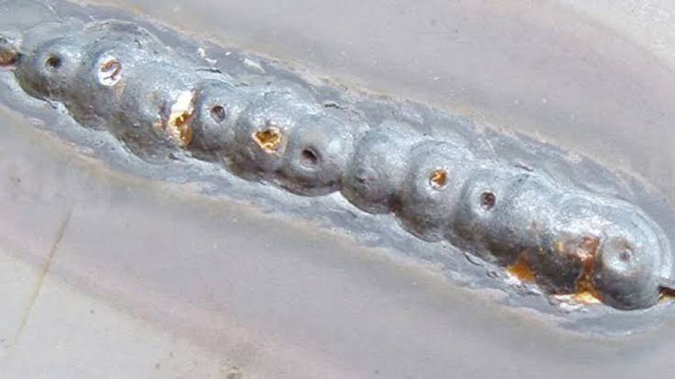
Image by mig-welding.co.uk
Why Thin Metal Demands Unique MIG Parameters
Thin materials (typically 24–16 gauge or 0.5–1.6 mm) conduct and dissipate heat poorly. Excess energy creates a large molten pool that drops through before solidifying. Voltage primarily controls arc length and heat width, while WFS (directly tied to amperage) governs deposition rate.
Mismatch either and you fight distortion or lack of fusion. Lower voltage and smaller wire diameters keep the puddle small and fast-freezing.
Wire Diameter Selection for Thin Metal Control
Wire diameter is the first decision that determines feasible settings.
0.023″ (0.6 mm) ER70S-6: Gold standard for 24–18 gauge mild steel. It melts at lower amperage (30–80 A range), allowing stable short-circuit transfer with minimal heat. Excellent wetting and deoxidizing on lightly contaminated surfaces.
0.030″ (0.8 mm): Suitable for 18–14 gauge or when more deposition is needed. Runs 50–120 A comfortably but requires tighter control on thinner stock to avoid burn-through.
0.035″ and larger: Generally avoided for true thin work; higher current demand increases risk on material below 1/16 inch (1.6 mm).
Always match contact tip and drive rolls to wire size. Use V-groove rolls for solid wire.
Shielding Gas and Flow Rates
75% Argon / 25% CO₂ (C25) delivers the best arc stability and lowest spatter for thin mild steel. Higher argon content softens the arc compared to 100% CO₂, reducing heat while improving bead wetting.
Flow rate: 15–20 CFH for most indoor setups. Increase slightly in drafts but avoid turbulence above 25–30 CFH.
For stainless thin sheet, consider tri-mix or 98% Ar / 2% CO₂ or O₂ mixes. Pure argon suits aluminum but demands different voltage/WFS.
Baseline MIG Settings Charts for Thin Metal
Use these as starting points on clean metal in flat position with DCEP polarity. Test on scrap identical to your workpiece.
Mild Steel ER70S-6 with C25 Gas (Short-Circuit Transfer)
| Thickness | Wire Diameter | Voltage (V) | WFS (IPM) | Approx. Amps | Gas Flow (CFH) | Travel Speed (IPM) |
|---|---|---|---|---|---|---|
| 24 ga (0.024″) | 0.023″ | 13–15 | 120–180 | 30–50 | 15–20 | 15–25 |
| 20 ga (0.036″) | 0.023″ | 14.5–16.5 | 140–220 | 50–70 | 18–22 | 12–20 |
| 18 ga (0.048″) | 0.023–0.030″ | 15.5–17 | 150–250 | 60–85 | 20–25 | 12–18 |
| 16 ga (0.060″) | 0.030″ | 16.5–18 | 180–280 | 70–95 | 20–25 | 10–16 |
| Up to ⅛” (0.125″) | 0.030″ | 17–18.5 | 180–300 | 90–125 | 20–30 | 8–14 |
Notes: For 100% CO₂, add 1–2 V. Flux-cored (e.g., E71T-GS) often uses DCEN polarity and runs slightly hotter—reduce settings 10–15% and expect more spatter/cleanup.
Fine-Tuning Voltage and Wire Feed Speed
Voltage sets arc length: too low causes stubbing and poor fusion; too high lengthens the arc, widens the bead, and risks burn-through or undercut. Start at the lower end of the range for thin metal.
WFS controls current/deposition. Increase WFS to add filler or improve penetration; decrease to reduce heat. Balance so the arc sounds like steady bacon frying—smooth and crackling, not popping or hissing loudly.
Adjustment Logic:
- Burn-through or excessive puddle: Drop voltage 0.5–1 V and/or WFS 20–30 IPM; increase travel speed.
- Lack of fusion or cold bead: Raise WFS slightly first, then match voltage.
- Erratic arc: Check stickout (3/8–1/2″ ideal for thin work), contact tip condition, and gas coverage.
Modern inverter machines with synergic or pulse modes simplify this—pulse allows higher peak current for fusion with lower average heat input, ideal for thin stainless or aluminum.
Heat Management Techniques
Continuous beads build heat rapidly on thin stock.
Stitch Welding: Weld ½–1 inch segments, pause ½–2 seconds (until red glow fades), then skip ahead 1–3 inches. Fill gaps after cooling. This reduces overall heat input by 20–40% while maintaining strength.
Skip Welding Pattern: Tack frequently, then weld short beads in alternating directions or locations to balance shrinkage and distortion.
Gun Technique:
- Push angle (10–15°): Directs arc force forward, flattens bead, and reduces heat concentration in the puddle.
- Consistent travel speed: Faster on thinner gauges (12–25 IPM) to limit dwell time.
- Maintain short, consistent stickout and steady hand motion. Weave minimally or use stringers.
Backing and Clamping: Copper or aluminum backing bars act as heat sinks. Secure fit-up tightly to minimize gaps that concentrate heat.
Material-Specific MIG Settings Adjustments
Mild Steel: Follow charts above. ER70S-6 handles minor surface contamination well.
Stainless Steel: Runs cooler—reduce voltage/WFS 10–15%. Use 0.023–0.030″ wire, tri-mix gas for best results on thin gauges. Short-circuit mode preferred; watch for distortion due to higher thermal expansion.
Aluminum: Requires pure argon, larger wire (0.030″ min), and higher WFS due to conductivity. Settings shift upward (e.g., 16–20 V range for thin sheet). Use spool gun or push-pull for feed consistency. Pulse helps dramatically.
Position and Joint Considerations
Flat position is easiest. For vertical or overhead on thin metal, drop voltage 1–2 V and WFS 10–15%, shorten stickout, and use smaller stitches. Lap joints tolerate more heat than butt joints; prepare edges cleanly and ensure good fit-up.
Troubleshooting Thin Metal MIG Welds
- Burn-Through: Immediate—lower settings, faster travel, shorter stitches, or add backing. Repair with copper-backed patches if needed.
- Porosity: Check gas flow, leaks, dirty metal, or excessive voltage causing turbulence.
- Undercut: Voltage too high or travel too fast; reduce voltage and ensure puddle fills toes.
- Excessive Spatter: Mismatched voltage/WFS, poor gas, or wrong polarity. Fine-tune balance and clean consumables.
Always test parameters on scrap. Machine charts inside the spool door provide good baselines but require real-world verification.
Real-World Application Insights
Successful MIG welding on thin metal comes down to deliberate heat control through wire size, low-end voltage, matched WFS, and interrupted techniques rather than chasing high deposition.
Prioritize 0.023″ solid wire with C25 gas for most indoor sheet work—it offers the widest forgiving window. For production or out-of-position, invest in machines with pulse capability.
On critical thin assemblies, calculate approximate heat input (kJ/in) using voltage, amperage, and travel speed formulas, then qualify procedures with bend or tensile tests on sample coupons. This separates hobby results from repeatable, code-worthy welds.
FAQ
What voltage and wire speed for MIG welding 18 gauge steel?
Use 0.023–0.030″ wire at 15.5–17 V and 150–250 IPM with C25 gas. Stitch weld with fast travel for best control.
Can you MIG weld thin metal with flux-cored wire?
Yes, but expect hotter arc and more spatter. Use DCEN polarity, lower settings, and accept extra cleanup. Solid wire with gas is superior for appearance and control on thin stock.
How do you prevent burn-through when MIG welding thin sheet?
Lower voltage first, use smallest suitable wire, employ stitch/skip patterns, push angle, fast travel, and backing. Test adjustments incrementally on scrap.
Does machine type affect thin metal MIG settings?
Inverter machines with pulse or synergic controls offer better low-amperage stability than older transformers. Start with manufacturer charts but always verify by sound and bead profile.