
At some point, every metalworking project reaches a stage where the surface needs to be cleaned, smoothed, or prepared for painting or welding. That raises a common question: does sandpaper work on metal, or is it only effective on wood and other softer materials?
The answer depends on the type of metal, the abrasive material, and—most importantly—the grit you choose. Using the wrong sandpaper can wear out quickly, leave deep scratches, or fail to remove rust, paint, or oxidation effectively.
On the other hand, selecting the proper abrasive improves surface finish, promotes better paint adhesion, and creates cleaner joints before welding or brazing.
Whether you’re restoring automotive parts, polishing stainless steel, or preparing mild steel for fabrication, understanding how sandpaper interacts with metal helps you achieve more consistent, professional-quality results while avoiding unnecessary effort and material waste.
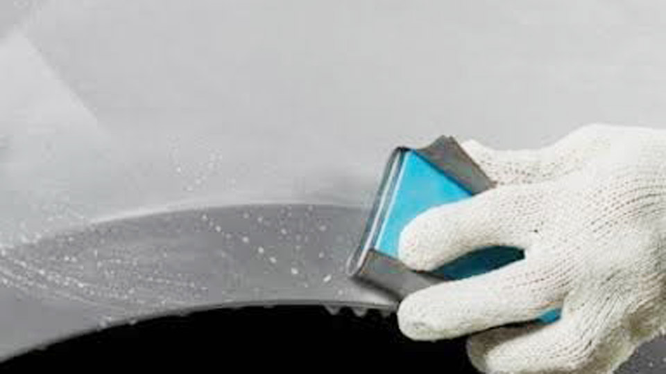
Image by protoolreviews
How Electrode Diameter Controls Heat Input and Penetration
Core-Wire Measurement Versus Overall Coating Thickness
Stick electrodes are sized by the diameter of the metal core wire, not the outer flux coating. A 1/8-inch (3.2 mm) E7018 and a 1/8-inch E7024 share the same core diameter even though the heavy iron-powder coating on the 7024 makes the overall rod thicker.
Always measure the bare end that clamps in the stinger. Common imperial sizes run 1/16 in (1.6 mm), 3/32 in (2.4 mm), 1/8 in (3.2 mm), 5/32 in (4.0 mm), 3/16 in (4.8 mm), and 1/4 in (6.4 mm). Metric equivalents follow the same progression.
Larger core diameter increases current-carrying capacity and therefore heat input. A 5/32-inch rod at 180 A delivers roughly twice the energy of a 3/32-inch rod at 90 A, producing a wider, deeper weld pool and higher deposition. That extra heat is useful on plate thicker than 1/4 in but becomes destructive on sheet metal.
Practical Diameter-to-Thickness Relationship
The working rule is straightforward: electrode diameter should stay between one-half and just under the base-metal thickness for single-pass work. On 1/8-inch plate a 3/32-inch rod is preferred; on 1/4-inch plate a 1/8-inch rod works cleanly.
Going larger than the plate thickness concentrates too much heat in a small volume and risks burn-through or severe warping. Going smaller than half the thickness forces multiple passes, raises the chance of slag inclusions, and slows production.
For material thicker than 3/8 in, most shops switch to a beveled joint and smaller electrodes rather than jump to 3/16-inch or 1/4-inch rods. The smaller rods keep the heat-affected zone manageable and allow better control of the root pass.
Arc Welding Rod Size Chart: Diameter, Amperage, and Thickness
General Starting Ranges Across Common Electrodes
The following table consolidates manufacturer data for the most frequently used mild-steel electrodes. Ranges overlap because flux chemistry, polarity, and machine characteristics shift the optimum point.
| Electrode Diameter | Typical Amperage Window | Suitable Plate Thickness | Notes |
|---|---|---|---|
| 1/16 in (1.6 mm) | 20–50 A | Up to 1/8 in | Limited machine stability below 30 A |
| 3/32 in (2.4 mm) | 40–125 A | 1/16–3/16 in | Most common DIY size |
| 1/8 in (3.2 mm) | 75–160 A | 1/8–1/4 in | Structural and farm work |
| 5/32 in (4.0 mm) | 110–220 A | 1/4–1/2 in | Requires 200 A+ machines for upper end |
| 3/16 in (4.8 mm) | 140–275 A | Over 3/8 in | High deposition, large puddle |
| 1/4 in (6.4 mm) | 200–350 A | Heavy plate, multi-pass fill | Industrial only |
These windows are starting points. Final amperage is dialed by listening to the arc and watching the puddle edges.
Type-Specific Amperage Adjustments
E6010 and E6011 (cellulose) run on the higher side of each diameter window because the aggressive arc needs extra energy to dig. A 1/8-inch 6010 typically sits between 90–140 A. E6013 (rutile) prefers the lower half of the range for its softer arc—80–120 A on the same 1/8-inch size.
E7018 (low-hydrogen) occupies the middle to upper portion, often 100–150 A for 1/8-inch, because the iron powder in the coating demands more current to maintain a stable spray-like transfer.
When the machine is AC-only, raise the set point 10 percent relative to the DC values listed on most packaging. Cold base metal also requires a modest increase; preheated plate allows a reduction.
Selecting Rod Size for Welding Position and Joint Geometry
Flat and Horizontal Work
In the flat position gravity assists the puddle, so the full recommended diameter and upper amperage range can be used. A 1/8-inch 7018 at 130–140 A lays a wide, flat bead with good sidewall fusion on 1/4-inch plate. Horizontal fillets tolerate the same size but often benefit from a 5–10 percent amperage drop to keep the toe from undercutting.
Vertical and Overhead Constraints
Vertical-up and overhead positions demand smaller diameters. The reduced deposition rate produces a smaller, faster-freezing puddle that resists dripping. Drop one size from the flat-position choice—use 3/32-inch instead of 1/8-inch on 1/4-inch plate—and reduce amperage another 10 percent.
Vertical-down (mostly 6010/6011) can run slightly higher current because travel speed is faster and the puddle is dragged rather than pushed.
Joint Configuration Effects
Butt joints with a small root opening need less heat than fillet welds of the same thickness; reduce amperage roughly 10 percent.
Outside corner joints require still less energy—another 5 percent drop—to avoid melt-through at the open edges. T-joints and lap joints behave more like fillets and accept the full diameter-and-amp combination.
Machine Output Limits and Practical Rod Choices
Matching Welder Amperage Capacity
Most portable inverter stick welders top out between 140 A and 200 A. That ceiling restricts usable rod size. A 160 A machine can run 1/8-inch electrodes comfortably at mid-range but will struggle with 5/32-inch rods once the duty cycle and open-circuit voltage are considered.
Larger industrial machines rated 300 A continuous can handle 3/16-inch and 1/4-inch electrodes for high-deposition fill passes.
Always verify the machine’s rated output at the duty cycle you intend to use. Running a 5/32-inch 7018 at 200 A on a 160 A nameplate machine forces the unit into thermal shutdown within minutes.
Multi-Pass Strategy on Thick Sections
When plate thickness exceeds the practical single-pass limit of the available machine, bevel both edges 30–37.5 degrees, leave a 1/16-inch land, and open a 1/16–3/32-inch root gap. The root pass is then made with a 3/32-inch or 1/8-inch electrode at moderate amperage.
Subsequent fill and cap passes can step up one size if the machine allows, or stay at the same diameter for maximum control. This approach keeps heat input per pass low, reduces distortion, and produces a stronger joint than a single oversized bead.
Interpreting Real-Time Arc Feedback to Fine-Tune Size and Amperage
Signs the Diameter or Amperage Is Too Low
The electrode sticks repeatedly, the arc extinguishes easily, the puddle remains narrow and fails to wet the sidewalls, and the slag is unusually dark and difficult to remove. Travel speed must be slowed dramatically to achieve any fusion.
These symptoms indicate either a rod that is undersized for the thickness or an amperage setting below the flux’s operating window.
Signs the Diameter or Amperage Is Too High
The electrode tip turns red within a few inches of travel, the arc becomes violent and noisy, spatter increases sharply, undercut appears along the toes, and the base metal begins to warp or burn through. The slag may glow red long after the bead freezes. Reduce current first; if the problem persists, drop one electrode size.
Experienced welders set the middle of the published range, strike a short test bead on scrap of the same thickness, and adjust 5–10 A at a time while watching the leading edge of the puddle.
A crisp, steady “frying-bacon” sound and a fluid crescent-shaped pool that freezes with a slight crown indicate the correct combination of size and current.
Advanced Decision Factors Beyond the Basic Chart
Storage and Condition of Low-Hydrogen Electrodes
E7018 and other low-hydrogen rods lose their low-hydrogen rating if they absorb moisture. Once the sealed can is opened, the electrodes should stay in a holding oven at 250–300 °F. Moisture-contaminated 7018 produces porosity that no amount of amperage adjustment can eliminate.
In field conditions where ovens are unavailable, many fabricators switch to cellulose or rutile electrodes of the same diameter rather than risk hydrogen cracking.
Deposition Rate Versus Control Trade-Off
Larger electrodes deposit metal faster, which shortens arc-on time on long seams. That advantage disappears in out-of-position work or on joints that require precise bead placement.
On critical structural connections the slower, more controllable smaller rod often produces higher radiographic quality even though total welding time increases.
Polarity and Its Interaction with Size
Most electrodes run best on DCEP (electrode positive). Switching to DCEN reduces penetration and can allow a slightly larger rod on thin material without burn-through, but the arc becomes less stable and slag control suffers.
AC machines require electrodes formulated for alternating current; the amperage window is usually shifted upward 10 percent relative to the DC chart.
When the variables of thickness, position, joint design, machine capacity, and electrode condition are all considered, the arc welding rod size chart becomes a living reference rather than a rigid rule.
The correct diameter is the one that keeps the puddle controllable while still delivering full fusion at a travel speed that matches the available heat input. Master that balance and the rest of the weld parameters fall into place.
FAQ
What size welding rod for 1/8 inch steel?
Use a 3/32-inch electrode for most single-pass work on 1/8-inch plate. A 1/8-inch rod is acceptable only if the joint is flat, the fit-up is tight, and amperage is kept at the low end of the range (approximately 80–100 A for 6013 or 90–110 A for 7018).
How many amps for a 1/8 inch 7018 rod?
Start between 100 A and 140 A on DCEP. Fine-tune by the sound and puddle appearance; most fabricators settle near 120–130 A for horizontal fillets on 1/4-inch material.
Can I use a 5/32 rod on a 160 amp welder?
Only at the extreme low end of the rod’s range (approximately 110–130 A) and only for short beads. Duty cycle will be limited, and the arc may lack the energy needed for full penetration on thicker plate. A 1/8-inch electrode is the safer choice on machines rated 160 A or less.
Does rod size change for overhead welding?
Yes. Drop one diameter size from the flat-position selection and reduce amperage 10 percent. The smaller puddle freezes faster and is less likely to drip.


