Many shops struggle when a conventional spot weld leaves inconsistent nuggets, rapid electrode wear, or visible marks on the show side of a part. That frustration often leads to the question of how does projection welding work and whether the process can solve those exact problems.
Projection welding concentrates current and force at pre-formed raised features on one workpiece, producing localized heat that collapses the projections and forms discrete weld nuggets or solid-state bonds.
The method matters because it enables multiple welds in one machine cycle, extends electrode life through large flat contact faces, and improves results on fasteners, thick-to-thin combinations, and parts that cannot tolerate surface indentation.
Understanding the sequence of force application, current flow, and projection collapse is the difference between a repeatable production process and costly rework.
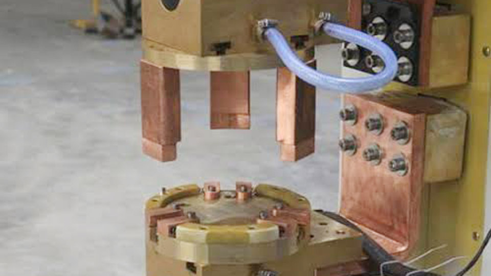
Image by kdmfab
What Actually Happens When Current Hits the Projection
Projection welding is a resistance welding process. Heat comes solely from the electrical resistance of the workpieces at the points of contact, not from an external arc. Force is applied before current begins, maintained during current flow, and held after current stops so the weld can forge and cool under pressure.
Current Concentration and Resistance Heating
The projections—embossed dimples, machined bosses, annular rings, or the corners of a weld nut—create the only initial contact points between the two parts. Because the contact area is small, current density rises sharply.
Resistance heating follows the relationship , so temperature at the projection tips climbs rapidly, often reaching forging or melting temperature within milliseconds. The surrounding bulk metal remains comparatively cool, limiting heat-affected zone size and distortion.
Projection Collapse and Nugget Formation
As the projection softens, electrode force collapses it. Molten or plastic metal from the projection mixes with the opposing surface. When current terminates, the force continues briefly, forging the interface and allowing solidification into a weld nugget (typical for embossed sheet-to-sheet joints) or a solid-state forge weld (common with solid projections on fasteners).
Displacement of the upper electrode during collapse is larger than in conventional spot welding; machine follow-up capability therefore becomes critical to maintain force as the projection height decreases.
Projection Design Choices That Control Weld Quality
Projection geometry dictates current density, collapse behavior, and final joint strength. Poor design produces incomplete set-down, expulsion, or weak interfaces.
Embossed vs Solid vs Annular Projections
Embossed (stamped) projections are formed in sheet metal and are the most common for sheet-to-sheet joints. A typical dome has a diameter-to-height ratio near 3:1 and must be rigid enough to support initial force without premature collapse.
Solid projections are machined or forged onto thicker parts or fasteners; they provide greater mass and often produce solid-state bonds rather than fusion nuggets. Annular (ring) projections create continuous circumferential seals and are used on hydraulic fittings or threaded bosses.
Crossed wires also function as natural projections and produce multiple welds simultaneously in products such as fencing or reinforcing mesh.
Height, Diameter, and Geometry Limits
Projection height is commonly 0.5–3 mm depending on sheet thickness. Height must be sufficient to concentrate current yet not so tall that the projection buckles under force before heating occurs. Base diameter and wall thickness control heat capacity.
Uniform height across multiple projections is essential; variation greater than a few tenths of a millimeter causes uneven current sharing and incomplete welds on the shorter projections. Fit-up and electrode parallelism become decisive when several projections are welded in one stroke.
Force, Current, and Time Interactions
The three primary process variables—electrode force, welding current, and weld time—must be balanced against projection geometry and material thickness. Incorrect combinations produce either cold welds or excessive expulsion.
Setting Electrode Force for Proper Collapse
Force is applied first so that only the projection tips make contact. Typical ranges run from approximately 2 kN to 20 kN total, scaled by the number of projections. Force should be high enough to break surface oxides and establish stable contact yet low enough that the projection does not collapse cold before current flows.
After the weld, a brief hold under force forges the joint. Machines with good follow-up maintain force as electrode displacement occurs during collapse; pneumatic systems with high inertia can lose force mid-cycle and produce incomplete bonds.
Current Density Requirements by Material and Thickness
Current is selected to raise the projection to welding temperature before it fully collapses. Values commonly fall between 8 kA and 40 kA total, again multiplied by the number of projections. Mild-steel embossed projections on 1–2 mm sheet often start in the 10–15 kA range per projection group.
Stainless and coated steels generally require higher current to overcome surface resistance. Aluminum needs still higher current and shorter times because of its high thermal and electrical conductivity.
Weld time is short—frequently 50–500 ms or even single-digit milliseconds on capacitor-discharge equipment—because heat generation is highly localized.
When Projection Welding Outperforms Spot Welding
The decision between projection and conventional spot welding turns on production volume, part geometry, and surface requirements rather than abstract preference.
Multiple Simultaneous Welds
Because the projections themselves define the weld locations, several discrete joints can be made in a single current pulse. This eliminates sequential electrode indexing and removes current-shunting problems that appear when spot welds are placed close together. Automotive weld-nut and stud applications routinely exploit this capability.
Fastener and Dissimilar Thickness Joining
Weld nuts, bolts, and brackets carry their own projections. Large flat electrodes contact the fastener and the sheet over a broad area, so electrode current density stays low and electrode life extends dramatically compared with the small tip required for spot welding.
The same principle allows reliable joining of thick-to-thin combinations: the projection is placed on the thicker or higher-resistivity member so heat generation remains balanced.
Machine and Electrode Requirements for Reliable Results
Projection welding machines share the same basic transformer and force system architecture as spot welders, yet several features become more critical.
Electrode Face Geometry and Cooling
Large, flat, or contoured copper-alloy electrodes match the part surface. Because contact area is large, current density and pressure at the electrode–part interface remain low, reducing wear and sticking. Water cooling is still required for continuous production, but electrode dressing intervals lengthen substantially.
Electrode faces must remain parallel; even modest angular misalignment causes uneven projection collapse when multiple projections are present.
Force Follow-Up and Process Monitoring
The dynamic nature of projection collapse demands rapid force response. Servo-electric or low-inertia pneumatic heads maintain contact pressure more consistently than high-inertia systems.
Displacement transducers that track electrode travel during the weld provide a useful process signature: the amount and rate of set-down correlate directly with projection collapse and nugget formation. Current and force monitoring further confirm that energy delivery stays inside the process window.
Wrapping Up
Projection welding succeeds when the part designer, tooling engineer, and process technician treat the projection as an integral process element rather than an afterthought. Geometry sets the current density, force sets the collapse rate, and machine follow-up converts that controlled collapse into a consistent joint.
When these three elements align, the process delivers multiple high-strength welds per cycle with minimal electrode maintenance and minimal marking on the non-projection side—capabilities that conventional spot welding cannot match at comparable production rates.
Advanced users further refine results by combining short upslope current profiles with precise force profiles, reducing expulsion while still achieving full set-down on coated or high-strength steels.
FAQs
What is the main difference between projection welding and spot welding?
Projection welding localizes current and force at pre-formed raised features on the workpiece; spot welding relies on the electrode tip geometry to concentrate current. Projection welding therefore supports multiple simultaneous welds and longer electrode life.
What current and force ranges are typical for projection welding?
Total currents commonly range from 8 kA to 40 kA and electrode forces from 2 kN to 20 kN, scaled by the number and size of projections. Exact values depend on material, thickness, and projection geometry.
Can projection welding join dissimilar thickness materials?
Yes. Placing the projection on the thicker or higher-resistivity member balances heat generation and produces reliable joints that are difficult with conventional spot welding.
Why do projection welds often show less surface marking?
Large flat electrodes contact the non-projection side over a broad area, so deformation and heat are concentrated on the projection side. The opposite surface remains relatively unmarked.