Choosing the wrong resistance welding process for sheet metal or fastener attachment often produces weak nuggets, excessive electrode wear, or surface indentation that fails appearance or strength requirements.
Understanding what is the difference between projection welding and spot welding prevents these failures by matching current concentration method, electrode design, and joint geometry to the actual production need.
Spot welding relies on electrode tip geometry to localize heat, while projection welding uses pre-formed raised features on the workpiece itself.
The distinction directly affects weld strength consistency, multi-point capability, electrode life, and allowable thickness ratios. Selecting correctly determines whether a single-cycle multi-weld assembly is possible or whether sequential single-point welding is required.
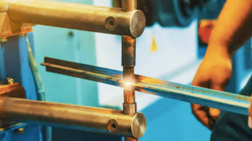
Image by kdmfab
How Current Concentration Differs Between the Two Processes
Resistance welding generates heat according to (I^{2}R), where current density at the faying surface controls nugget formation. The location of that concentration is the fundamental process difference.
Electrode-Driven Concentration in Spot Welding
In resistance spot welding, copper-alloy electrodes with domed or truncated-cone faces contact the outer surfaces of the stacked sheets. Current flows through the electrode-to-sheet interface and concentrates at the sheet-to-sheet contact zone under the electrode tip.
Typical tip face diameters range from 4–8 mm for mild steel sheets up to about 3 mm thick. Force is applied through the same electrodes (commonly 2–8 kN depending on thickness), and weld times are short—often 5–20 cycles at 60 Hz. Heat generation occurs primarily at the faying surfaces because interface resistance is highest there.
Projection-Driven Concentration
Projection welding places one or more deliberately formed projections (embossments, solid projections, or annular rings) on one of the workpieces. Flat, large-faced electrodes apply force and current. Current density is highest at the small contact area of each projection tip.
As the projection heats, softens, and collapses under electrode force, the contact area expands while a weld nugget forms. Because the projection itself controls current path, electrode contact area can be much larger, reducing current density at the electrode face and lowering wear.
Electrode Design and Force Requirements That Drive Process Choice
Electrode geometry and required force capacity separate the equipment and tooling needs of each process.
Pointed or Domed Electrodes for Spot Welding
Spot welding electrodes must maintain a precise contact diameter to control nugget size. Wear or mushrooming of the tip changes current density and produces inconsistent welds, so frequent tip dressing or replacement is required.
Force is concentrated on a small area, producing higher local pressure and visible indentation on both outer surfaces. Machines range from portable guns to pedestal units; secondary current demands are moderate for thin sheet but rise quickly with thickness.
Flat Electrodes and Higher Total Force for Projection Welding
Projection welding uses large, flat electrodes that contact a broader area. Individual projection contact stress is high at the start of the weld cycle, but total electrode force must be high enough to collapse all projections simultaneously and maintain uniform pressure.
Multi-projection welds therefore demand machines with greater force capacity and more rigid platens to keep electrodes parallel. Electrode life is significantly longer because current density at the electrode face remains low. Surface marking on the non-projection side is minimal when flat electrodes are used.
Thickness Capability and Joint Design Limitations
Material thickness and thickness mismatch determine which process remains practical.
Thin-Sheet Limits of Spot Welding
Spot welding performs reliably on mild steel and coated steels in the 0.5–3 mm range for single sheets, occasionally up to 6–8 mm with high-capacity machines. Thickness ratios greater than about 3:1 become difficult because heat balance shifts toward the thicker sheet and fusion on the thinner side suffers.
Multi-sheet stacks are possible but limited by shunting and heat balance. Edge distance and weld spacing must allow adequate current flow without excessive shunting through previously made welds.
Expanded Thickness Range with Projections
Projection welding handles greater thickness mismatches—ratios of 6:1 or higher are routine because the projection localizes heat independently of sheet thickness. Solid projections on fasteners allow welding of nuts, studs, or brackets to thin sheet without burning through the sheet.
Embossed projections on sheet-to-sheet joints permit closer spacing and smaller overall joint overlap than equivalent spot welds. Multi-layer stacks benefit from the controlled collapse of each projection.
Production Speed and Multi-Weld Capability
Cycle time and number of simultaneous welds affect throughput decisions.
Sequential Single-Point Spot Welding
Each spot weld is made individually. Robotic or multi-gun systems can fire several guns nearly simultaneously, but each gun still produces one nugget.
Shunting becomes a concern when welds are placed close together; minimum spacing is typically 10–25 mm depending on sheet thickness and conductivity. High-volume body shops rely on dozens of guns per station to achieve rate.
Simultaneous Multi-Point Projection Welding
Multiple projections on a single part or fastener can be welded in one machine cycle provided electrode force and current are distributed uniformly. This eliminates sequential shunting problems and reduces total cycle time for assemblies containing several attachment points.
Typical examples include welding three- or four-projection weld nuts in a single stroke or attaching brackets with multiple embossed projections. Machine power and force capacity must scale with the number of projections.
Surface Appearance, Spatter, and Electrode Maintenance Outcomes
Visible quality and consumable cost differ measurably between the processes.
Indentation and Marking in Spot Welding
The small electrode tip produces a clear indentation on both outer surfaces. On Class A surfaces this may require subsequent finishing. Spatter risk rises if force is insufficient or current is excessive.
Electrode dressing intervals are short—often every few hundred to a few thousand welds on coated steels—raising consumable and downtime cost.
Minimal Marking and Longer Electrode Life in Projection Welding
Because heat and force are concentrated at the projections, the opposite sheet surface remains essentially unmarked when flat electrodes are used. Spatter is generally lower once parameters are optimized for projection collapse.
Electrode faces wear slowly; dressing or replacement intervals are substantially longer, lowering maintenance cost in high-volume fastener welding.
Application Decisions That Separate the Processes
Real production choices follow joint function more than abstract process descriptions.
When Spot Welding Is the Practical Selection
Body-in-white sheet metal joining, HVAC ductwork, appliance cabinets, and general thin-gauge fabrication favor spot welding. Geometry is simple, no projection forming step is required, and equipment cost is lower for low-to-medium volume.
Portable guns allow access to closed structures. When welds must be made in corners or against edges where a projection cannot seat properly, spot welding remains the workable option.
When Projection Welding Delivers Clear Advantages
Attachment of weld nuts, studs, captive fasteners, and brackets to sheet is the classic projection welding application. Electrical contacts, cross-wire welding, and assemblies requiring multiple precise welds in one cycle also favor projections.
When thickness mismatch is large, when surface appearance on one side is critical, or when electrode life must be maximized, projection welding is selected. Automotive seat frames, chassis brackets, and appliance hardware routinely use the process.
Parameter Relationships and Process Sensitivity
Both processes operate within the same resistance-welding family, yet the allowable parameter window differs.
Spot Welding Parameter Flexibility
Electrode force, current, and time can be adjusted over a relatively wide band. Force must be high enough to contain the molten nugget yet low enough to avoid excessive indentation. Current and time are balanced to achieve the required nugget diameter (typically 4–6 mm for 1 mm sheet) without expulsion. Coated steels require higher force and adjusted current schedules to manage zinc or aluminum coatings.
Projection Welding Sensitivity to Projection Geometry
Projection height, diameter, and shape must be consistent. Excessively high or soft projections collapse before adequate heat is generated; undersized projections may not produce full fusion. Force must be sufficient to collapse all projections at approximately the same rate.
Current and time are usually shorter than equivalent spot welds because heat is already localized. Parallelism of electrodes and uniform projection height become critical for multi-point consistency.
Wrapping Up
Selecting between the two processes reduces to a set of concrete questions: Does the joint require pre-formed projections or fasteners? Is multi-point welding in one cycle needed? What thickness ratio and surface appearance are required? Is electrode maintenance cost a dominant factor? When projections can be designed into the part and machine force capacity is available, projection welding provides higher consistency, longer electrode life, and multi-weld efficiency.
When geometry is simple, thickness is modest, and access or flexibility matters more, spot welding remains the lower-cost, more adaptable choice.
Advanced production lines often combine both processes on the same assembly—spot welding the primary sheet joints and projection welding the fasteners—to optimize each connection type.
FAQs
What is the main difference between projection welding and spot welding?
Projection welding concentrates current through pre-formed raised projections on the workpiece and uses flat electrodes; spot welding concentrates current through the geometry of pointed electrodes contacting the sheets directly.
Can projection welding make multiple welds at once?
Yes. Multiple projections can be welded simultaneously in a single machine cycle if electrode force and current are distributed evenly across all projections.
Which process is better for welding nuts to sheet metal?
Projection welding is preferred for weld nuts and similar fasteners because the projections on the nut control heat location, produce consistent strength, and leave minimal marking on the opposite side of the sheet.
Is projection welding suitable for thin sheet only?
No. Projection welding handles greater thickness mismatches and thicker combinations than conventional spot welding because the projection localizes heat independently of overall sheet thickness.