Aluminum’s oxide layer melts near 3700°F while the base metal melts around 1220°F. That mismatch produces dirty, peppered puddles, sudden burn-through, or tungsten contamination the moment settings or technique drift.
TIG welding aluminum tips and tricks center on controlling AC balance, frequency, heat input, and gas coverage so the cleaning action removes oxide without destroying the electrode or overheating thin edges.
Get these variables wrong and the weld fails radiographically or visually long before the joint cools. Correct decisions on tungsten geometry, filler chemistry, and travel rhythm turn the same process into repeatable, high-integrity results across sheet, plate, and castings.
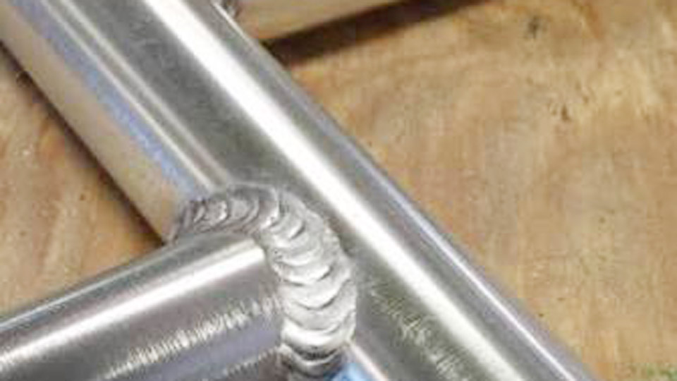
Image by weldingtipsandtricks
How to Dial AC Balance and Frequency for Oxide Removal Without Killing the Tungsten
AC balance sets the ratio of electrode-negative (penetration) to electrode-positive (cleaning). Frequency shapes the arc cone and heat distribution.
Starting Balance Values That Match Surface Condition
Most modern inverters display percent electrode-negative. Begin at 65–75% EN (25–35% cleaning) on clean, freshly brushed material. This range delivers a visible etched zone roughly 1/16–1/8 inch outside the toes while keeping the tungsten cool enough to hold a truncated or small ball tip.
Drop toward 60–65% EN when the puddle shows black flecks or gray film—more EP time increases oxide scrubbing. Raise above 75% EN only on perfectly prepared, thin material where maximum penetration and minimal etch are required. Excessive EP enlarges the ball, destabilizes the arc, and shortens electrode life.
Frequency Choices That Control Arc Width and Heat Spread
Higher frequency (150–200 Hz) tightens the arc cone, reduces heat-affected zone, and improves directional control on sheet under 1/8 inch or near edges. Lower frequency (60–100 Hz) widens the arc, increases total heat input, and helps wrap corners on thicker plate or outside-corner joints.
A practical all-around starting point on most inverter machines is 100–120 Hz. Drop below 80 Hz only when amperage is limited and deeper penetration is needed; raise above 150 Hz when burn-through risk is high or the joint is tight.
Waveform Interaction With Balance and Frequency
Square-wave output concentrates energy and supports higher EN percentages with less tungsten heating than older sine-wave machines. Independent EN/EP amperage control (available on advanced inverters) lets you run high penetration current while limiting cleaning current, further protecting the electrode on thick sections.
Tungsten Selection and Tip Geometry for Stable AC Arcs
Electrode choice and preparation determine arc stability and contamination risk far more than many operators realize.
Alloy Recommendations by Machine Type
Pure tungsten (green) forms a stable ball and remains acceptable on older transformer machines at moderate amperage. Zirconiated (brown or white) resists spitting better and carries higher current while still balling cleanly—preferred for traditional AC equipment.
On modern square-wave inverters, 2% lanthanated (blue) or 1.5% lanthanated (gold) electrodes hold a truncated point longer, provide superior arc starting, and work across both AC aluminum and DC steel without changing electrodes. Ceriated electrodes also function but lose performance faster at high AC amperage.
Diameter Versus Amperage Matching
Use 1/16 inch for currents below roughly 100 A, 3/32 inch for 100–200 A, and 1/8 inch or larger above 200 A. Undersized tungsten overheats, balls excessively, and drops particles into the puddle. Oversized tungsten requires higher starting amperage and can produce a softer, less controllable arc at low current.
Tip Preparation Differences Between Transformer and Inverter
Transformer machines traditionally run a fully balled tip. Inverter machines perform better with a truncated or slightly blunted point ground longitudinally; the point focuses the arc while still allowing a small ball to form under AC load. Never use a razor-sharp point intended for DC steel work—AC cleaning action will melt it back unevenly.
Filler Metal Decisions: 4043 Versus 5356 and When Strength or Appearance Wins
Filler chemistry affects crack resistance, strength, anodizing response, and high-temperature service.
4043 Silicon Alloy Strengths and Limits
ER4043 flows easily, resists hot cracking, and tolerates imperfect cleaning better than magnesium alloys. It is the default for most 6xxx-series extrusions and castings. Welds appear smoother and produce less soot.
Drawbacks include lower as-welded strength (especially in fillets) and a dark gray response after anodizing. Avoid sustained service above approximately 150°F if magnesium-bearing alternatives are available, though 4043 itself handles elevated temperature better than 5356.
5356 Magnesium Alloy Strengths and Limits
ER5356 delivers higher tensile and shear strength, better ductility in structural fillets, and superior color match after anodizing. It is required for most 5xxx-series base metals containing more than about 2.5% magnesium and preferred for marine or high-load applications.
The puddle is less fluid, demands cleaner base metal, and can show more soot. Do not use 5356 for prolonged exposure above 150°F because of stress-corrosion risk.
Practical Selection Rules
On 6061 that will be anodized, choose 5356. On the same alloy for non-anodized structural work or when crack resistance is primary, 4043 remains safer. For pure strength in fillets, one pass of 5356 often equals three passes of 4043.
Always match filler diameter to base thickness—typically one size smaller than the tungsten for thin material and equal or one size larger for plate.
Amperage Ranges and Heat-Management Strategies by Thickness
Aluminum’s thermal conductivity demands higher starting amperage than steel of equal thickness and continuous adjustment with a foot pedal.
Starting Amperage Windows
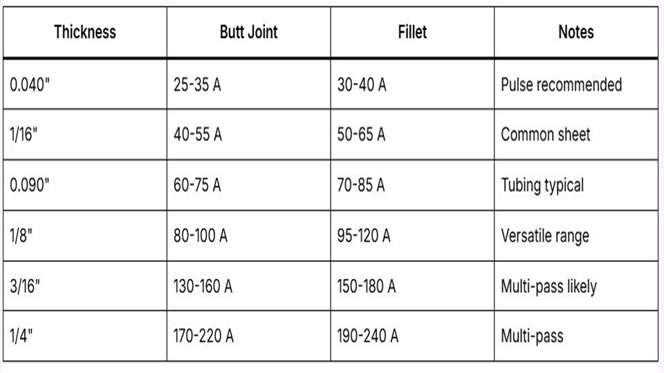
A working rule is roughly 1–1.2 A per 0.001 inch of thickness, adjusted upward for fillets and T-joints that conduct heat in multiple directions. Typical ranges:
| Thickness | Amperage Range (AC) | Notes |
|---|---|---|
| 1/16 in | 60–100 A | High frequency, fast travel |
| 1/8 in | 110–160 A | Most common shop thickness |
| 3/16 in | 150–220 A | Consider light preheat |
| 1/4 in | 200–275 A | Lower frequency, larger tungsten |
Outside-corner joints often run 10–20% lower; heavy fillets or cold material run higher. Use the pedal to start near the top of the range and reduce as the part heats.
Preheat and Heat-Sink Decisions
Sections thicker than 3/16 inch benefit from 150–250°F preheat to reduce thermal gradient and improve wetting. Copper backing bars or chill plates pull heat from the reverse side on thin sheet and prevent burn-through. Continuous long beads without pauses allow heat to build; break long seams into shorter segments when distortion control is critical.
Gas Flow, Cup Size, and Coverage That Eliminate Pepper and Gray Welds
Shielding integrity is non-negotiable. Contaminated argon or inadequate coverage produces oxide inclusions immediately visible in the puddle.
Cup Size and Flow Relationships
Standard ceramic cups #5 to #8 cover most work. Gas-lens kits improve laminar flow and allow slightly lower rates or longer stick-out. A practical starting formula is 2–3 CFH times the cup number (e.g., #6 cup at 12–18 CFH).
Thin material and tight joints favor smaller cups and lower flow; thicker plate and open joints accept larger cups and 20–25 CFH. Excessive flow creates turbulence that aspirates air; insufficient flow leaves the tungsten and puddle unprotected.
Post-Flow and Pre-Flow Timing
Set post-flow long enough for the tungsten to cool below oxidation temperature—typically 8–15 seconds depending on amperage. Short post-flow leaves a black, contaminated tip that must be re-ground. Pre-flow of 0.5–1 second ensures coverage before the arc starts.
Torch Angle, Arc Length, and Filler Timing That Preserve Edges and Prevent Cold Laps
Technique variables interact directly with machine settings.
Arc Length and Angle Discipline
Maintain an arc length roughly equal to the tungsten diameter. Longer arcs increase voltage, widen the bead, and reduce cleaning efficiency.
A 10–15° push angle keeps the arc force directed into the joint and allows filler addition in the leading edge of the puddle. Vertical and overhead positions require even tighter arc control and slightly reduced amperage.
Filler Addition Rhythm
Dip the filler into the leading edge of the puddle, not the arc column. On thin material, add small, frequent dabs synchronized with foot-pedal peaks. On thicker plate, continuous feed or larger dabs maintain the required deposition rate.
Withdraw the rod slightly between dips to avoid freezing it into the puddle. Keep the filler tip inside the gas envelope at all times.
Pulse Parameters for Thin Aluminum and Heat-Sensitive Joints
Pulse reduces average heat input while still providing peak energy for fusion.
Practical Starting Pulse Values
Peak amperage set at or slightly above the continuous equivalent. Background 25–50% of peak. Frequency 0.5–5 pulses per second for manual work (higher frequencies feel continuous). Pulse width 30–50%.
The classic “rule of 33” (33 PPS, 33% background, 33% width) provides a useful training rhythm on sheet. Raise peak amperage above the non-pulse value because the average heat is lower. Pulse is most valuable on material under 1/8 inch, outside corners, and joints with limited heat sink.
Wrapping Up
Successful aluminum TIG work rests on matching AC balance and frequency to surface condition and thickness, selecting tungsten and filler for the specific alloy and service requirements, and controlling heat with pedal, travel, and gas coverage.
Once those decisions are locked, the remaining variables—arc length, filler timing, and pulse—become fine adjustments rather than rescue attempts.
Advanced operators further improve consistency by recording exact balance, frequency, and gas-flow numbers for each recurring joint geometry, then verifying oxide cleanliness with a dedicated stainless brush immediately before welding; residual oxide is the single most common source of porosity that no machine setting can fully overcome.