Spot welding often fails when parameters are guessed rather than calculated, leading to weak nuggets, expulsion, electrode damage, or inconsistent production. Spot welding parameters calculations provide the precise electrode force, current, time, and geometry needed for reliable fusion across material thicknesses and types.
These calculations matter because heat input follows Joule’s law (Q = I²Rt), where small errors in current or force amplify defects in the nugget formation, especially in thin sheets or coated materials common in automotive and fabrication work.
Proper calculations ensure nugget diameter meets the 5√t rule (where t is sheet thickness in mm), balancing strength with minimal distortion. For DIY welders, students, and professionals, mastering these delivers repeatable results without trial-and-error waste.
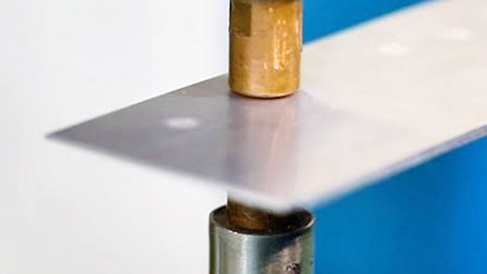
Image by resistance-welding
Core Principles of Heat Generation and Nugget Formation
Joule’s Law Application in Spot Welding
Heat generation in resistance spot welding depends on current squared, resistance, and time. Contact resistance at faying surfaces dominates initially, decreasing as temperature rises and force deforms asperities. Bulk resistance grows with temperature due to resistivity increase.
For low-carbon steel, target nugget diameter approximates 5√t mm. Electrode face diameter should exceed this slightly (typically 1–2 mm larger) to contain the molten pool.
Dynamic Interactions Between Parameters
Increasing force lowers contact resistance and current density, requiring higher current for the same heat. Longer weld time compensates for lower current but risks heat diffusion and larger HAZ. Calculations must iterate these variables for specific stack-ups.
Calculating Electrode Force
Force Requirements Based on Material and Thickness
Electrode force ensures intimate contact and controls current density. A general target is around 90 N/mm² of electrode contact area. For two sheets of equal thickness t (mm), force scales with thickness and material hardness.
Typical values for mild steel (from standard tables):
- 0.8 + 0.8 mm: 2.24 kN
- 1.0 + 1.0 mm: 2.50 kN
- 1.5 + 1.5 mm: 3.65 kN
- 2.0 + 2.0 mm: 5.00 kN
For higher-strength steels (350–700 MPa), increase force by 10–20% to counter springback and maintain contact.
Cylinder Pressure to Force Conversion
Use this formula for pneumatic systems:
Force (lbs) ≈ 0.78 × D² × P
Where D = piston diameter (inches), P = air pressure (psi).
To find required pressure:
P = Force / (0.78 × D²)
Example: For 600 lbs force with a 3-inch piston: P ≈ 85 psi. Always verify with machine calibration, as friction losses occur.
Adjustments for Coated and Dissimilar Materials
Galvanized steel requires higher initial force to break through coatings, then possible reduction. Aluminum needs significantly higher force (often 2–3x steel) due to lower resistivity and higher thermal conductivity.
Determining Weld Current and Time
Current Calculation Guidelines
Current is the dominant heat driver. Start with empirical ranges and adjust:
For mild steel (approximate RMS values):
- 1.0 mm: 9,500 A
- 1.5 mm: 10,450 A
- 2.0 mm: 11,200 A
- 3.0 mm: 12,350 A
Use the relationship: Higher force demands proportionally higher current. Monitor for expulsion as the upper limit.
For three-phase or inverter machines, actual delivered current differs from single-phase AC due to waveform. Measure with a current meter for accuracy.
Weld Time Selection and Cycles
Weld time (cycles) relates to thickness: roughly 10 × t (in mm) for 50 Hz systems. At 60 Hz, reduce cycles accordingly.
Convert cycles to seconds:
Time (ms) = Cycles / Frequency
Pulsation (multiple short pulses) helps for thicker materials (>2 mm) or AHSS to control heat buildup and reduce expulsion. Example for 2 mm: 3 pulses of 7–9 cycles with cool times.
Hold time (post-weld) allows nugget solidification: 1–6 cycles typical, longer for coated or crack-sensitive materials.
Power and Duty Cycle Considerations
Transformer sizing uses:
kVA = (I × V) / 1000 (single-phase).
Duty cycle derates capacity: P_x = P_max × √(Duty Cycle). High-production setups rarely exceed 10–20% duty, preventing overheating.
Electrode Geometry and Face Diameter Calculations
Sizing Electrode Tips
Electrode contact diameter d ≈ 5√t + 1–2 mm. Standard for 0.5–1.25 mm steel: 6 mm face.
As tips mushroom, diameter grows, reducing current density. Recalculate or dress tips to maintain parameters. Truncated cone or dome shapes common; flat faces for precision.
Material Selection for Electrodes
RWMA Class 2 copper suits most steel. Class 1 for aluminum (higher conductivity). Consider hardness vs. conductivity trade-offs for wear resistance.
Parameters for Specific Materials
Low-Carbon and Mild Steel
Follow standard tables closely. Coated (galvanized) versions need 10–20% higher current/time initially due to coating resistance, then stabilization.
Advanced High-Strength Steels (AHSS)
Higher strength demands adjusted schedules with pulsation to avoid cracking. Use AWS C1.1 guidelines: coated parameters preferred. Increase force and use shorter times/higher currents for martensitic grades.
Aluminum Alloys
Aluminum’s low resistivity and high conductivity require high current (often 15–25 kA), short times (3–10 cycles), and high force. Surface preparation critical; oxide layer increases variability. Electrode sticking common—frequent dressing or special alloys needed.
Stainless Steels
Higher resistivity allows lower current than mild steel but longer times. Watch for sensitization in 300-series.
Step-by-Step Parameter Calculation Workflow
- Identify stack-up: materials, thicknesses, coatings.
- Determine target nugget size: 5√t (single sheet) or adjusted for multi-sheet.
- Select electrode: diameter, material, shape.
- Calculate initial force: ~90 N/mm² × contact area; adjust for material.
- Estimate current from tables or I ≈ k × √(t) scaling (empirical k varies).
- Set time: start short, increase until nugget forms without expulsion.
- Test weld, section or peel test, iterate (increase current 5–10% increments).
- Document for production, including squeeze/hold times.
This workflow minimizes destructive testing while achieving consistent button size and shear strength.
Advanced Calculations and Automation Insights
Heat Balance in Dissimilar Thickness or Materials
Heat generation biases toward higher resistivity or thinner sheet. Compensate with electrode geometry (larger face on thicker side) or current pulsing.
Software and Simulation Aids
Modern tools model thermal-electrical-mechanical interactions, predicting nugget growth. Input material properties (resistivity vs. temp, thermal conductivity) for optimization before physical trials.
Production Scaling Factors
Account for electrode wear: force/current may need ramping. Duty cycle and cooling affect machine capability. For robotics, parameter consistency across guns requires servo or adaptive controls.
Troubleshooting Parameter-Related Defects
Expulsion and Surface Indentation
Caused by excessive current/time or insufficient force. Reduce current or increase force; shorten time.
Cold Welds (Undersized Nugget)
Increase current or time; check electrode alignment and contact.
Cracking or Brittle Nuggets
Common in high-carbon or AHSS. Extend hold time for slower cooling or add post-heat temper cycle.
Electrode Sticking/Mushrooming
Improper force/current balance or dirty surfaces. Optimize parameters and implement tip dressing schedule.
Real-World Decision Framework for Parameter Selection
Match calculations to application: structural (larger nugget, higher strength) vs. cosmetic (minimal indentation). Prioritize peel/shear testing over visual. For variable production, develop parameter families by thickness ranges rather than single-point settings.
Performance-Based Takeaway
Accurate spot welding parameters calculations transform welding from art to engineered process. The interplay of force reducing resistance while current drives heat demands iterative, data-backed decisions tailored to each stack-up.
Professionals who master these achieve superior joint efficiency, electrode life, and throughput—key differentiators in competitive fabrication.
An advanced insight: integrating real-time current monitoring with adaptive control systems allows dynamic adjustment mid-weld, pushing nugget consistency beyond static tables.
FAQ
What is the 5√t rule in spot welding?
It defines minimum nugget diameter as 5 times the square root of the thinnest sheet thickness (in mm). It serves as a practical quality benchmark for fusion zone size and strength.
How do I calculate weld time from cycles?
Divide cycles by line frequency: ms = cycles / 50 (Europe) or /60 (North America). Example: 12 cycles at 60 Hz = 200 ms.
Why does galvanized steel need different parameters?
Zinc coating alters contact resistance and melts early, requiring higher initial force/current adjustments and often longer hold times to manage expulsion and alloying.
Can the same parameters work for aluminum as steel?
No. Aluminum demands much higher current, shorter times, and greater force due to its physical properties. Use material-specific tables and frequent electrode maintenance.