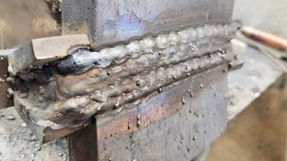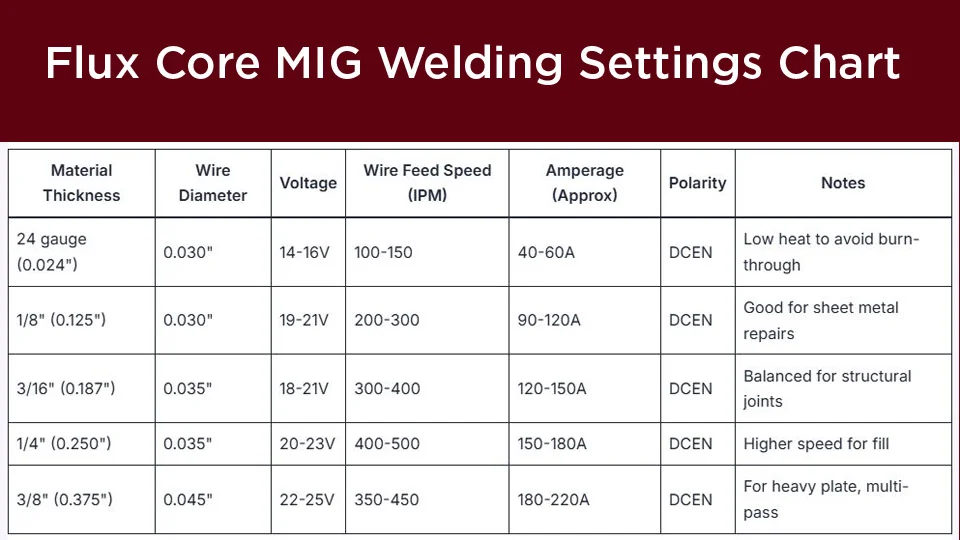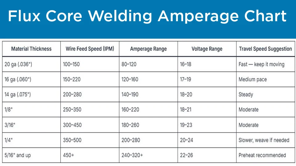
Burn-through appears within the first second when heat input exceeds the thermal capacity of 22-gauge steel. Many operators assume any flux-core setup that works on 16-gauge will simply scale down, only to watch the puddle drop through the sheet and leave a hole larger than the intended bead.
Welding 22 gauge steel with flux core demands a deliberate reduction in energy density, strict polarity control, and discontinuous technique because self-shielded FCAW inherently deposits more heat than solid-wire MIG at equivalent parameters.
The difference between a usable lap joint and scrap is often 1–2 volts or 10–15 IPM of wire feed. Correct decisions on wire diameter, machine polarity, and travel sequence determine whether the joint reaches fusion without distortion or melt-through.
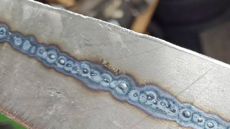
Image by r/Welding
Wire Diameter and Classification Limits for 22-Gauge Material
Self-shielded flux-cored wire must melt at the lowest practical current while still generating enough slag coverage. Diameter selection is the first filter.
Why 0.030-Inch Wire Is the Practical Maximum
0.030-inch (0.8 mm) E71T-11 or E71T-GS wire draws roughly 30–80 A across the usable voltage window on most 110–120 V machines. Larger 0.035-inch wire typically requires 80–120 A even at its lowest stable settings, which exceeds the heat sink capacity of 0.030-inch base metal.
Manufacturer data sheets for common E71T-11 products list minimum usable thicknesses around 20 gauge; running below that rating is an operator choice, not a published capability.
Classification Differences That Affect Thin Sheet
E71T-11 wires are formulated for all-position work and produce a fluid slag that freezes relatively quickly. E71T-GS variants often emphasize single-pass performance and may run slightly hotter at the same wire-feed speed.
Both require DC electrode negative (DCEN). Using DCEP reverses the heat balance, placing more energy into the base metal and accelerating burn-through.
Spool and Drive-Roll Considerations
Knurled drive rolls sized for flux-core prevent crushing the tubular wire. Contact tips must match the 0.030-inch diameter exactly; an oversized tip increases stick-out variability and arc instability at the low currents required.
Machine Polarity, Voltage, and Wire-Feed Windows
Self-shielded flux core operates on constant-voltage power sources. Voltage primarily sets arc length; wire-feed speed largely determines amperage.
DCEN Polarity Requirement
Flip the polarity leads so the gun is negative and the work clamp is positive. This places approximately two-thirds of the arc energy into the wire rather than the sheet. Failure to reverse polarity from a previous solid-wire setup is the most common cause of immediate melt-through on 22-gauge material.
Starting Parameter Bands for 0.030-Inch Wire
On typical 110–120 V machines the workable range collapses to a narrow band:
| Parameter | Starting Range | Adjustment Direction for Burn-Through |
|---|---|---|
| Voltage | 14–16 V | Lower first |
| Wire feed speed | 40–70 IPM | Reduce 5–10 IPM |
| Approximate amperage | 35–70 A | Controlled by WFS |
| Contact-tip-to-work | ⅜–½ inch | Lengthen slightly to drop current |
| Travel speed | 12–18 IPM | Increase |
Higher-output 220 V machines can reach the same low currents but often require the lowest voltage tap and careful inductance settings if available. Always verify actual output with a clamp meter if the machine dials are unmarked or worn.
Stick-Out Influence on Effective Current
Increasing stick-out from ⅜ to ⅝ inch raises resistance heating in the wire and reduces the current delivered to the arc by 10–15 A at constant wire-feed speed. This technique provides fine control when voltage taps are coarse.
Joint Design and Fit-Up Decisions That Reduce Heat Input
Joint geometry dictates how much metal must be melted and how heat dissipates.
Lap and Flange Joints Preferable to Butt Joints
A tight lap joint places two thicknesses under the arc, doubling the heat sink relative to a square butt. Edge flanges or hemmed edges further increase local mass. Open butt joints on 22-gauge sheet leave almost no margin; any gap larger than 1/32 inch invites melt-through.
Backing Bars and Heat Sinks
Copper or aluminum backing bars clamped tightly against the reverse side extract heat and support the molten pool. The backing must be clean and dry; residual moisture generates porosity. When backing is unavailable, temporary steel backup strips can be tacked and later ground away.
Gap and Edge Condition
Edges must be square, free of burrs, and tightly fitted. Mill scale or paint under the joint increases the energy required for fusion and raises the risk of incomplete penetration or porosity.
Technique Sequences That Limit Cumulative Heat
Continuous beads deposit more energy than the thin sheet can conduct away. Discontinuous methods are mandatory.
Stitch and Skip Welding Pattern
Place ½-inch to ¾-inch stitch welds spaced 1–2 inches apart. Move to a distant section of the joint before returning. Allow each stitch to cool to warm-to-the-touch before placing the next adjacent stitch. This sequence keeps peak interpass temperature low enough to avoid warping.
Trigger-Tapping for Extreme Thin Sections
For the thinnest areas or critical cosmetic panels, depress the trigger only long enough to form a small molten pool (0.3–0.5 second), then release. Overlap successive spots by 30–50 percent. The method produces a series of overlapping nuggets rather than a continuous bead and further reduces total heat input.
Gun Angle and Travel Direction
Maintain a 5–15 degree drag angle so the slag trails the puddle. Push angles force slag ahead of the arc and increase inclusion risk. Vertical-down travel is preferred over vertical-up because the faster freeze reduces sag and heat soak.
Distortion Control and Post-Weld Correction Limits
Even correctly parameterized welds introduce residual stress. Prevention outweighs correction on 22-gauge sheet.
Clamping and Fixturing Requirements
Clamp the work to a heavy steel table or fixture that acts as a heat sink. Spacing clamps every 4–6 inches along long seams limits out-of-plane movement. Release clamps only after the entire joint has returned to ambient temperature.
Measurement of Distortion During Welding
Check flatness with a straightedge after every third or fourth stitch. If the panel begins to oil-can, stop, allow full cooling, and adjust the skip sequence or reduce wire-feed speed further.
Limits of Mechanical Straightening
Light hammering over a dolly can remove minor waves, but repeated cold working work-hardens the heat-affected zone and risks cracking. Excessive heat input that produces visible warpage usually requires cutting out the joint and restarting with revised parameters.
When Flux Core Should Be Abandoned for Thin Sheet
Self-shielded FCAW remains a compromise on 22-gauge material. Process selection is a technical decision, not a preference.
Comparison with Solid-Wire Short-Circuit MIG
ER70S-6 solid wire of 0.023 or 0.024 inch diameter run with 75 % argon / 25 % CO₂ at 40–60 A produces lower heat input, less spatter, and cleaner beads. The external gas shield allows tighter control of arc energy. When appearance or minimal distortion is required, solid-wire MIG is the superior choice.
TIG as the Precision Alternative
Gas-tungsten arc welding with 1.0–1.6 mm tungsten and matching filler wire permits amperage control down to 20–40 A with pedal modulation. Heat input can be held below the burn-through threshold more reliably than any constant-voltage process. TIG is slower but eliminates slag and reduces residual stress.
Decision Criteria
Use flux core only when outdoor wind, lack of gas supply, or portability outweighs the higher risk of defects. For indoor shop work on visible panels, switch processes.
Wrapping Up
Successful welding of 22-gauge steel with flux core hinges on accepting the process limits rather than forcing parameters developed for thicker material. Select 0.030-inch E71T-11 wire, reverse to DCEN, stay inside the 14–16 V / 40–70 IPM window, and interrupt every bead.
When those constraints still produce melt-through, the correct technical response is to change processes rather than chase marginal settings.
Advanced operators treat 22-gauge flux-core work as a heat-management exercise first and a deposition exercise second, measuring interpass temperature and distortion after every short sequence to keep the panel within geometric tolerance.
FAQs
What wire size is best for flux core on 22-gauge steel?
0.030-inch E71T-11 or E71T-GS self-shielded wire is the largest diameter that routinely stays within a safe heat-input range. Larger wire increases burn-through risk.
What polarity is required for self-shielded flux core on thin sheet?
DC electrode negative (DCEN). The gun must be connected to the negative terminal so most of the arc energy heats the wire instead of the base metal.
Can flux core weld 22-gauge steel without burn-through?
Yes, but only with low voltage (14–16 V), reduced wire-feed speed, short stitch welds, and frequent cooling. Many manufacturers do not list 22 gauge as a supported thickness for self-shielded wires.
Should I use flux core or solid-wire MIG for 22-gauge panels?
Solid-wire MIG with 0.023–0.024-inch wire and argon-rich gas provides better heat control and cleaner results. Use flux core only when gas shielding is unavailable.