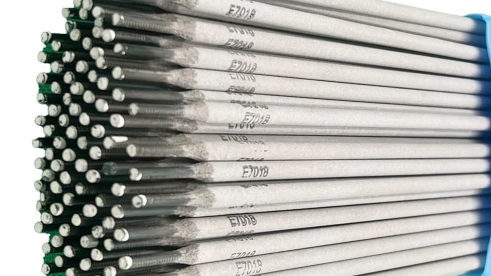
Wrong amperage on a 1/8″ 7018 rod produces immediate failures: the electrode sticks repeatedly at low settings, or the bead undercuts and spatters heavily when the current runs too high.
A reliable 7018 1/8 welding rod amperage chart eliminates that trial-and-error cycle by giving measurable starting points that match the electrode’s low-hydrogen iron-powder coating to real joint conditions.
Correct heat input determines penetration depth, slag release, and resistance to hydrogen cracking—critical for structural steel, pressure vessels, and certified work.
Settings outside the proven range of roughly 90–160 A destroy arc stability and deposit integrity long before visual inspection reveals the damage. Dialing in the right current first keeps every subsequent variable—travel speed, angle, and interpass temperature—under control.
Exact Amperage Ranges for 1/8″ 7018 by Welding Position
Lincoln Excalibur data lists 90–160 A on DCEP and 100–160 A on AC for 1/8″ (3.2 mm) E7018. Field practice narrows those windows by position because gravity and puddle fluidity change heat requirements.
Flat and Horizontal Fillet and Groove Settings
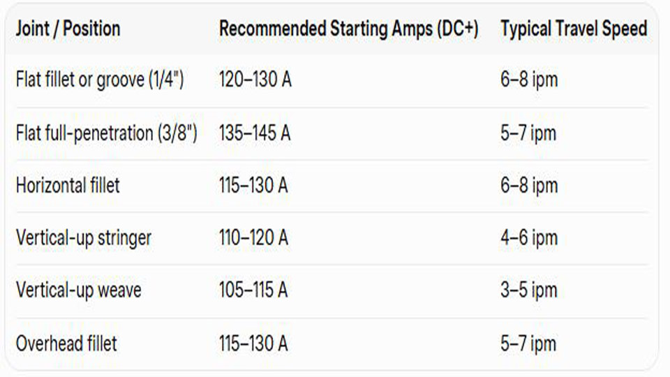
Start at 120–140 A for most ¼” to ⅜” mild-steel plate. At 125–130 A the arc produces a quiet hiss, a fluid oval puddle, and a bead roughly 2.5 times the core-wire diameter.
Raise toward 150 A only when full-penetration butt joints on ⅜” or thicker material demand deeper fusion. Horizontal fillets respond well to the same band; excess current creates undercut on the upper toe.
Vertical-Up Stringer and Weave Adjustments
Drop 10–15 % from the flat setting. Most operators settle between 105–120 A. The lower heat keeps the slag from running ahead of the puddle and allows a slight side-to-side or triangular weave without undercut.
On open-root 3G tests, 115 A with a short arc often produces the required root penetration into the backing bar while still freezing the sideshell quickly enough to avoid sagging.
Overhead Control and Heat Management
Overhead favors the upper half of the vertical range or slightly higher—typically 115–130 A—because the shorter arc and faster freeze help support the molten metal. Going above 140 A increases the chance of dripping slag and porosity at the crater.
Maintain an arc length no longer than the electrode diameter and use a slight drag angle to keep the force of the arc pushing metal upward into the joint.
Matching Amperage to Base-Metal Thickness with 1/8″ 7018
Thickness governs heat sink and required fusion depth more than any other single variable once position is fixed.
Sections Thinner Than ¼”
Limit current to 90–115 A. On 3/16″ material the lower end prevents burn-through while still achieving fusion. Short arc length and moderate travel speed compensate for the reduced amperage; a long arc at low current produces only surface melting and lack of fusion.
Medium Plate from ¼” to ⅜”
The 110–140 A window covers nearly all single- and multi-pass work. A ¼” T-joint fillet typically runs cleanly at 120–125 A. For a single-pass butt joint on ⅜” plate with a 60° included angle, 135–145 A supplies the needed root penetration without excessive reinforcement.
Heavier Material and Multi-Pass Sequences
On ½” and thicker plate the 1/8″ rod still works for root and fill passes at 140–160 A, but deposition rate becomes the limiting factor. Many shops switch to 5/32″ after the root once the groove opens.
When staying with 1/8″, keep interpass temperature within the WPS limits and clean thoroughly between layers; residual heat from previous passes effectively raises the working amperage felt by the next bead.
Polarity and Power-Source Effects on 7018 Arc Behavior
E7018 operates on both AC and DC, yet polarity alters penetration profile and arc force.
DC Electrode Positive Preference
DCEP concentrates roughly two-thirds of the heat at the workpiece. The result is deeper penetration, tighter arc column, and cleaner starts. Virtually every manufacturer recommends DCEP as the primary polarity for 1/8″ 7018. Arc force is higher, which helps dig into mill scale or light rust without increasing current.
Running on AC-Only Machines
AC requires a 5–10 % increase in set amperage—commonly 110–160 A—to maintain comparable arc stability. The continuous polarity reversal softens the arc and can produce a slightly wider, flatter bead.
Modern inverters with AC output often include arc-force or dig controls that restore some of the DC-like characteristics; older transformer machines lack that compensation and demand tighter operator technique.
Interaction of Travel Speed, Arc Length, and Amperage
Amperage alone never determines bead quality; the three variables form a closed system.
Short-Arc Technique at Recommended Currents
Keep the electrode tip almost in contact with the puddle—arc length approximately equal to core-wire diameter. At 120–130 A this produces the characteristic quiet, concentrated arc of 7018 and minimizes atmospheric nitrogen and oxygen pickup. Lengthening the arc at the same amperage widens the bead, increases spatter, and raises the risk of porosity.
Travel-Speed Windows Linked to Current
At 115 A expect travel speeds around 4–6 inches per minute for stringers; at 140 A the same bead profile can be maintained at 7–9 ipm. Faster travel at fixed amperage reduces heat input and can leave incomplete fusion at the toes. Slower travel increases reinforcement height and the chance of slag inclusions if the operator weaves excessively.
Quick Starting Points (Most Common Shop Settings)
Diagnosing Amperage Errors from Bead Appearance and Arc Sound
Visual and auditory feedback arrives faster than any meter reading once the arc is established.
Indicators of Insufficient Current
The rod sticks frequently, the arc extinguishes on contact, and the bead appears ropey with high reinforcement and poor toe fusion. Slag freezes tightly and requires aggressive chipping. Increase current in 5 A increments until the arc stabilizes and the slag lifts cleanly after cooling.
Indicators of Excessive Current
The electrode tip glows red beyond the coating, the arc produces loud crackling and heavy spatter, and undercut forms along both toes. The bead flattens excessively and may show porosity or crater cracking.
Reduce current and increase travel speed simultaneously; simply lowering amperage without adjusting speed often leaves a cold-looking but still undercut bead.
Storage and Moisture Control Relative to Amperage Performance
Low-hydrogen coatings lose their protective value when moisture content rises. Damp electrodes force operators to raise amperage in a futile attempt to burn out porosity, which only worsens undercut and heat input.
Hermetically sealed cans or a holding oven at 250–300 °F keep the coating within specification. Reconditioning procedures follow manufacturer limits—typically one bake cycle at higher temperature—because repeated heating degrades the flux and alters the effective operating range.
Decision Framework for Selecting Final Amperage on the Job
Begin with the manufacturer’s mid-range value for the chosen polarity and position. Run a short test bead on scrap of identical thickness and joint geometry. Evaluate fusion by sectioning or by grinding a face and checking for incomplete penetration. Adjust in 5 A steps while recording travel speed and arc length.
Once the bead profile, slag release, and sound match the target, lock the setting and note ambient temperature, machine type, and electrode lot for future reference.
This empirical calibration accounts for machine calibration drift, cable length voltage drop, and slight differences between electrode brands that charts cannot capture.
Wrapping Up
Choosing the correct point inside the 90–160 A band for a 1/8″ 7018 electrode is ultimately a balance of penetration demand against puddle control. When the arc produces a steady hiss, the slag peels cleanly, and the toes blend without undercut, the current is right for that joint.
Advanced operators further refine heat input by combining short-arc technique with deliberate stringer-bead sequencing rather than wide weaves, preserving mechanical properties and reducing the risk of hydrogen-assisted cracking on high-restraint joints.
FAQs
What amperage should I run for 1/8″ 7018 vertical up?
Most vertical-up work settles between 105–120 A on DCEP. Start at 115 A and adjust downward if the slag runs ahead of the puddle.
Can I run 1/8″ 7018 on an AC-only stick welder?
Yes. Increase the setting 5–10 % above the DC value—typically 110–160 A—and maintain a short arc to compensate for the softer AC arc.
What is the best starting amperage for 1/4″ mild steel with 1/8″ 7018?
120–130 A on DCEP in the flat position gives reliable fusion and clean slag release for both fillet and groove welds.
How do I know if my 7018 amperage is too high?
Look for a glowing electrode tip, heavy spatter, undercut at the toes, and a loud, crackling arc. Reduce current 5–10 A and increase travel speed.