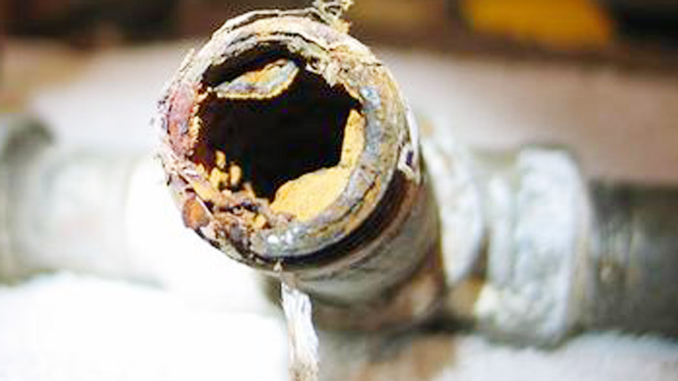
A cracked gray iron engine block or manifold often fails again after a quick steel-rod repair because the weld zone hardens, residual stresses spike, and the brittle graphite-flake structure cannot absorb the contraction.
Learning how to weld gray cast iron correctly starts with recognizing that the material’s high carbon content (typically 2.5–4 %) and low ductility demand controlled heat input, compatible fillers, and deliberate cooling rates.
Without those controls the heat-affected zone forms hard carbides or martensite, and the joint cracks under service loads.
Proper electrode selection, preheat, short-bead technique, and slow cooling convert an otherwise high-risk repair into a durable, often machinable joint that restores structural integrity on pump housings, gear cases, and machine bases.
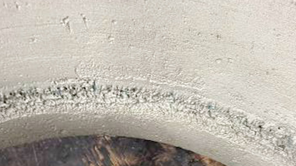
Image by fb/I See You Don’t Know Shit About Welding
Identifying Gray Cast Iron Before You Strike an Arc
Visual and Fracture Clues That Confirm the Alloy
Gray cast iron fractures with a dull, dark-gray surface caused by free graphite flakes. The spark test produces short, reddish sparks with few branches, unlike the longer, brighter sparks of ductile iron or steel. Surface appearance is usually coarse and may show casting marks or sand residue.
Confirming the type matters because gray iron tolerates nickel fillers well but reacts poorly to high-dilution steel deposits.
Carbon Content and Phosphorus Effects on Weld Behavior
Higher phosphorus levels increase hot-cracking risk in pure-nickel deposits. When phosphorus is elevated, nickel-iron electrodes (ENiFe-CI) tolerate the contamination better than pure-nickel (ENi-CI) rods.
Thickness and section complexity further dictate preheat level: thin, open sections can run cooler, while thick, restrained sections require higher, more uniform heat to equalize expansion.
Selecting Filler Metal and Welding Process for Gray Iron
Nickel-99 Versus Nickel-55 Electrodes
ENi-CI (approximately 99 % nickel) produces the softest, most machinable deposit and handles high dilution on single-pass repairs. ENiFe-CI (roughly 55 % nickel, 45 % iron) delivers higher tensile strength, greater ductility, lower thermal-expansion mismatch, and better tolerance of phosphorus.
Use Nickel-99 when post-weld machining of thin or precision surfaces is required; choose Nickel-55 for thicker multi-pass work, structural repairs, or cast-iron-to-steel joints.
Steel-core electrodes (ESt) or mild-steel rods create hard, crack-prone deposits and should be reserved for emergency, non-machined, low-stress applications only.
Why SMAW Dominates Gray-Iron Repair
Shielded-metal-arc welding with the electrodes above remains the most practical process for field and shop repairs. It delivers concentrated heat, works in all positions with proper technique, and requires only modest equipment.
TIG can serve thin or precision sections with nickel filler rods when absolute cleanliness and low heat input are possible. MIG with nickel wire is feasible in short-circuit mode but demands stricter heat management and is less forgiving of contamination.
Establishing Preheat Temperature and Uniformity
Temperature Ranges by Section Thickness
For medium-size gray-iron castings, a preheat of 500–600 °F (260–315 °C) is typical with nickel electrodes. Thin sections may tolerate 300–400 °F; heavy or complex sections often require 700–1 200 °F.
Do not exceed approximately 1 400 °F, which enters the critical temperature range and risks further microstructural damage. Interpass temperature is normally held below 600–650 °F to avoid excessive residual stress.
Applying and Monitoring Heat Without Creating New Stresses
Heat the entire casting whenever possible, preferably in a controlled oven or with multiple torches and insulating blankets. Localized torch heating must be gradual and even; rapid surface heating on thick sections creates expansion gradients that crack the iron before welding begins.
Temperature sticks or infrared thermometers confirm uniformity. Maintain the preheat throughout the welding sequence.
Preparing the Joint to Minimize Dilution and Contamination
Cleaning Requirements Specific to Cast Iron
Graphite, oil, and foundry sand must be removed completely. Grind or arc-air gouge the crack or defect to sound metal, forming a V- or U-groove with rounded root edges. Extend the cleaned zone at least ½–1 inch beyond the repair area.
Degrease with solvent after grinding; residual oil produces porosity even with nickel fillers. Drill stop-holes at crack ends on thin sections to prevent propagation during heating.
Groove Geometry and Stud Reinforcement Decisions
A 60–90° included angle with a slight root radius reduces stress concentration. On thick or highly restrained sections, inserting threaded studs into the prepared faces before welding increases joint strength by transferring load into the base metal rather than relying solely on the fusion line.
Executing the Stick-Welding Sequence on Gray Cast Iron
Amperage, Polarity, and Electrode Diameter Choices
Use the smallest practical electrode diameter—commonly 3/32 in or 1/8 in—to limit heat input. Typical current ranges on DCEP (or AC) are 40–80 A for 3/32 in and 70–110 A for 1/8 in with nickel electrodes; always stay at the low end that still produces wetting.
DC electrode negative can further reduce penetration and dilution when available. Avoid hot-start and high arc-force settings that inject extra heat.
Bead Length, Skip Technique, and Sequence
Deposit short stringer beads, usually ½–2 inches long, then stop. Skip to another area of the joint so the casting never experiences continuous heat buildup in one location. Back-step or alternate sides on long cracks. Direct the arc primarily onto previously deposited weld metal rather than the base iron to keep dilution low.
Controlling Residual Stress Through Peening and Cooling
Timing and Force of Peening
While the bead is still red-hot, lightly peen the deposit with a ball-peen hammer or pneumatic tool. Peening plastically deforms the weld metal, relieving tensile stresses that would otherwise crack the joint on cooling. Over-peening or peening after the metal has cooled below dull red is ineffective and can introduce new damage.
Slow-Cooling Methods That Preserve Softness
After the final pass, cover the entire casting with dry sand, vermiculite, or insulating blankets and allow it to cool to ambient temperature over many hours. Rapid air cooling recreates the hard, brittle heat-affected zone the preheat was intended to prevent. For critical parts, a controlled post-weld stress-relief cycle in a furnace further improves results.
Evaluating When Cold Welding or Alternative Processes Apply
Limits of No-Preheat or Low-Preheat Procedures
Short beads, continuous peening, and nickel electrodes can produce acceptable results on small, lightly restrained castings without formal preheat.
The heat-affected zone remains harder and the long-term crack resistance is lower than a properly preheated weld. Reserve cold techniques for non-critical or emergency field repairs where uniform heating is impossible.
TIG and Oxy-Fuel Roles
TIG with ERNi-CI or ERNiFe-CI filler suits thin, clean sections when pulse capability keeps heat input minimal. Oxy-acetylene fusion welding with cast-iron rods and high preheat (often 1 000–1 200 °F) can restore near-base-metal color and machinability but is slower and less practical for most modern repairs.
Wrapping Up
Successful gray-iron welds hinge on matching filler ductility to the base metal, keeping heat input and dilution low, and forcing the cooling rate slow enough to avoid hard microstructures.
Choose Nickel-55 for most structural multi-pass work and Nickel-99 when machinability is non-negotiable; maintain uniform preheat in the 500–600 °F range for typical sections; restrict beads to short lengths with immediate peening; and never allow rapid cooling.
Advanced practice further reduces risk by combining root passes of pure nickel with fill passes of nickel-iron, balancing softness at the fusion line against overall joint strength under cyclic loading.
FAQs
Can you weld gray cast iron without preheating?
Yes, with nickel electrodes, short beads under 1 inch, immediate peening, and intermittent welding that keeps the part from overheating. The HAZ will be harder and the repair less reliable under high stress or thermal cycling than a preheated joint.
What is the best welding rod for gray cast iron?
ENiFe-CI (Nickel-55) for general structural repairs and higher strength; ENi-CI (Nickel-99) when the weld must be easily machined. Both outperform steel-core rods for crack resistance.
What amperage should I use for 1/8-inch nickel rod on cast iron?
Stay in the 70–110 A range on DCEP or AC, favoring the lower end that still produces good wetting and a controllable puddle. Higher current increases dilution and cracking risk.
How do I cool gray cast iron after welding?
Cover the entire casting with insulating material or dry sand and allow it to reach room temperature slowly over several hours. Rapid cooling recreates brittle structures in the heat-affected zone.