Porosity, unstable arcs, and wasted cylinders almost always trace back to one point: incorrect gas delivery. Learning how to hook up gas to MIG welder systems prevents air contamination at the nozzle and keeps the shielding envelope stable from the first trigger pull.
A loose regulator, wrong CGA fitting, kinked hose, or flow set while the solenoid is closed produces measurable defects long before the bead looks wrong.
Proper cylinder restraint, regulator attachment, hose routing, and flow calibration deliver consistent coverage at 15–30 CFH for most mild-steel short-circuit work and eliminate the most common source of rejectable porosity.
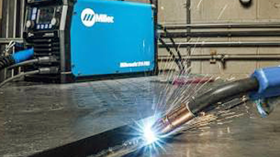
Photo by millerwelds
Selecting the Right Regulator and Fittings for Your Gas Cylinder
Cylinder pressure and gas type dictate the regulator interface. Using the wrong CGA connection or a pressure-only gauge instead of a flowmeter creates either leaks or inaccurate readings that ruin weld quality.
CGA Connections for Common MIG Gases
Argon and argon-CO₂ mixes (C25, C10) use CGA-580 fittings. Pure CO₂ cylinders use CGA-320. Many argon-rated regulators require a CGA-320 adapter plus the plastic washer when switching to 100 % CO₂.
The adapter must seat fully; missing the washer produces a high-pressure leak at the cylinder valve. Never force mismatched threads—brass seats deform and will not seal later.
Flowmeter Versus Pressure Gauge Preference
MIG shielding requires volumetric flow in cubic feet per hour (CFH), not downstream pressure in PSI. A dual-stage regulator with a ball-type flowmeter tube gives stable readings once gas is moving. Single-stage units drift as cylinder pressure drops.
The high-pressure gauge simply shows remaining cylinder contents (typically 2000–2200 psi full for argon mixes). Set flow only while gas is flowing through the system; a static reading is meaningless.
Securing the Cylinder and Preparing the Valve
An unsecured cylinder is a projectile hazard and a contamination source. Proper positioning and cleaning of the valve seat protect both the operator and the regulator.
Cylinder Restraint and Orientation
Chain or strap the cylinder upright to a wall, cart, or dedicated rack at two points—upper and lower. Never leave a freestanding bottle. Remove the protective cap only after the cylinder is secured.
Position the valve outlet away from the work area so any sudden release does not direct gas or debris toward the operator.
Cracking the Valve Before Regulator Attachment
With the cylinder valve closed and the regulator still off, stand to the side and open the valve for one-half second, then close it. This clears dust, scale, or packing residue from the seat.
Perform the crack outdoors or in strong ventilation. Debris that enters the regulator body scores the seat and produces intermittent flow errors that appear as porosity only after several welds.
Attaching the Regulator and Gas Hose
Metal-to-metal or washer seals are designed into CGA fittings. Adding thread tape usually creates more problems than it solves.
Regulator Installation Sequence
Back the regulator adjusting screw fully counterclockwise (closed position) before attachment. Hand-thread the CGA nut onto the cylinder valve, then tighten with a smooth-jaw wrench—never overtighten. Brass is soft; excessive force deforms the seat.
Once the regulator is mounted, connect the gas hose to the regulator outlet. Most US machines accept a 5/8-18 right-hand female fitting on the hose end that mates to a male stud on the welder’s gas inlet. Hand-tighten the collar plus a quarter turn; an O-ring or nylon washer completes the seal on modern units.
Hose Routing and Machine Inlet Connection
Route the hose without sharp bends or pinches. Kinks reduce effective flow even when the flowmeter reads correctly. On the machine end, push the fitting fully onto the gas inlet stud until it seats against the O-ring, then tighten the collar.
Some older machines use a hose-barb and clamp; in that case use a stainless clamp and verify the barb is fully inserted. Confirm the hose is rated for inert gas service—standard air hose can outgas plasticizers that contaminate the weld.
Opening the System and Setting Correct Flow Rate
Flow must be adjusted under actual delivery conditions. Setting the ball while the solenoid is closed produces an optimistic reading that collapses once welding begins.
Safe Cylinder Valve Opening
Stand to the side of the regulator face. Open the cylinder valve slowly until fully open, then back it off one-half turn.
Full open prevents seat leakage past the packing; the half-turn allows rapid shut-off in an emergency. The high-pressure gauge should jump to cylinder pressure. Listen and feel for immediate leaks at the CGA connection.
Establishing Flow and Reading the Meter
Most machines open an internal gas solenoid only when the trigger is pulled. Use the machine’s gas-purge function if available, or pull the trigger with the wire drive disabled (or gun pointed safely away) so gas flows without feeding wire.
Adjust the flowmeter while gas is moving until the ball centers on the target CFH. Typical indoor mild-steel short-circuit values with C25 are 18–25 CFH.
Raise to 30–35 CFH for light drafts or larger nozzles; outdoor or windy conditions may require 35–45 CFH, though wind barriers are preferable to extreme flow rates that induce turbulence.
Flow Rate Reference by Condition
| Condition | Recommended CFH (C25 / mild steel) | Notes |
|---|---|---|
| Still indoor air | 18–25 | Standard short-circuit |
| Light shop draft / fan | 25–35 | Increase until porosity stops |
| Outdoor / open door | 35–45 | Use wind screen if possible |
| Aluminum (100 % Ar) | 20–30 indoor / 30–40 outdoor | Higher flow stabilizes spray |
| Larger nozzle (⅝ in+) | Add 5–10 CFH | Coverage area increases |
Leak Testing and System Purge Before Welding
Undetected leaks waste gas and admit air at the worst possible location—the nozzle.
Soap-Solution Leak Check
With the cylinder open and flow set, spray or brush soapy water (or commercial leak detector) on every connection: CGA nut, regulator outlet, hose ends, and machine inlet. Bubbles indicate leakage.
Close the cylinder valve, bleed residual pressure, tighten or replace the leaking component, then retest. Never use oil-based solutions near oxygen equipment, although MIG shielding gases are inert.
Purging Air from the Hose and Gun
Air trapped in a newly connected hose or after a cylinder change contaminates the first several inches of weld. Hold the trigger (gas only) for 3–5 seconds until pure shielding gas exits the nozzle.
On machines without a dedicated purge button, this is the only reliable method. After any interruption longer than a few minutes, a short purge prevents start porosity.
Diagnosing Gas Delivery Problems After Hookup
When porosity appears despite correct flowmeter readings, the fault usually lies downstream of the regulator.
Solenoid and Gun Path Checks
Confirm the solenoid clicks when the trigger is pulled. No click points to trigger circuit, control board, or power issues. Gas flowing continuously after trigger release indicates a stuck solenoid.
Weak flow at the nozzle with correct regulator reading often means a restricted diffuser, clogged nozzle, damaged O-rings inside the gun, or a partially collapsed liner. Remove the nozzle and diffuser and inspect for spatter buildup that blocks gas ports.
Environmental and Technique Interactions
Excessive stick-out length or too high a travel speed can outrun the gas envelope even at correct CFH. Drafts from open doors or cooling fans displace the shield; relocate the work or add simple barriers. On thin material, lower flow slightly to reduce cooling and turbulence while still maintaining coverage.
Wrapping Up
Correct gas hookup is complete only when the cylinder is restrained, the regulator and hose are leak-free, flow is set under actual delivery conditions, and the system has been purged. Once those conditions exist, the shielding envelope remains consistent across the usable range of wire feed speeds and voltages for the process.
Advanced operators further reduce gas consumption by matching nozzle diameter to joint access and by using post-flow timers on machines that offer them, extending coverage a fraction of a second after the arc extinguishes to protect the cooling crater without continuous high flow.
FAQs
What CFH should I set for MIG welding mild steel indoors?
Start at 20 CFH with C25 gas and a standard ½-inch nozzle. Increase only if porosity appears or a light draft is present.
Do I need Teflon tape on the regulator fitting?
No. CGA fittings seal metal-to-metal or with the supplied washer. Tape can shred and contaminate the gas path.
Why is there no gas at the nozzle even though the regulator shows pressure?
The machine solenoid opens only on trigger. Check for a stuck or failed solenoid, kinked hose, or blocked diffuser after confirming the cylinder valve is fully open.
Can I use the same regulator for pure CO₂ and argon mixes?
Only with the correct CGA adapter and washer for CO₂. Argon regulators are not designed for the different density and potential freeze-up of pure CO₂ without proper adaptation.