Successful automotive repairs depend on more than replacing damaged panels; they require welding techniques that restore proper fit, strength, and alignment without excessive heat distortion.
Understanding the 5 essential auto body repair welding techniques helps you choose the right approach for different materials, panel thicknesses, and joint configurations.
Thin automotive sheet metal is particularly challenging because excessive heat can cause burn-through, warping, and unnecessary grinding, while insufficient fusion can compromise joint strength.
Techniques such as MIG plug welding, butt welding, lap welding, tack welding, and stitch welding serve different purposes during collision repair and panel replacement.
Applying each method correctly helps control heat input, maintain panel geometry, and produce joints suitable for the repair. Whether you’re a DIY automotive enthusiast or a professional technician, knowing when and how to use these techniques can improve repair quality, reduce rework, and support reliable results.
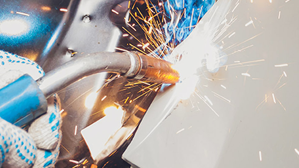
Image by bodyshopbusiness
Which MIG Settings Prevent Burn-Through on 18-22 Gauge Body Panels?
Short-circuit MIG remains the primary process for most mild-steel outer skins, floor pans, and non-structural patches because it deposits metal quickly at low heat when the parameters stay tight.
Wire Diameter and Gas Choices That Control Heat
Use 0.023-inch or 0.024-inch ER70S-6 solid wire. Larger 0.030-inch wire demands higher current to melt and pushes heat deeper into the sheet, raising burn-through risk on anything thinner than 18 gauge. Shielding gas should be 75 % argon / 25 % CO₂ (C25).
Straight CO₂ runs hotter and produces more spatter; pure argon lacks the penetration needed for reliable fusion on mill-scale steel. Gas flow of 15–20 CFH keeps the puddle protected without turbulence that draws in air.
Voltage and Wire-Speed Windows for Different Gauges
Start with these ranges on a machine capable of fine voltage adjustment and test on identical scrap:
| Gauge | Thickness (in) | Voltage | Wire Speed (ipm) | Approx. Amps |
|---|---|---|---|---|
| 22 | 0.030 | 13–15 | 90–130 | 30–50 |
| 20 | 0.036 | 15–16 | 120–150 | 50–70 |
| 18 | 0.047 | 16–17 | 140–180 | 60–85 |
Stickout stays between ⅜ and ½ inch. Longer stickout lowers effective heat but destabilizes the arc. Push the gun 10–15 degrees in the direction of travel for a flatter bead and less penetration depth.
Stitch and Skip Sequences That Limit Distortion
Never run a continuous bead longer than ½–¾ inch on outer panels. Place a short tack or stitch, move 2–4 inches away, and allow the metal to cool until it can be touched comfortably. Alternate sides of a long seam so heat never concentrates in one zone.
Copper backing bars or clamps drawn tightly against the joint act as heat sinks and further reduce warpage. The finished series of overlapping stitches should read as a continuous seam after grinding yet never heated the panel enough to oil-can.
When Does a Plug Weld Replace a Factory Spot Weld?
Plug (rosette) welds restore overlapping flanges where a resistance spot welder cannot reach both sides or where the repair procedure explicitly permits substitution.
Hole Size, Spacing, and Penetration Requirements
Drill or punch 5/16-inch (8 mm) holes in the outer panel when the flange width allows; some procedures specify ⅜-inch. Space the holes to match the original spot-weld pattern or the OEM count listed in the body repair manual—typically 1 to 1½ inches center-to-center on structural members.
The weld must completely fill the hole and fuse into the lower panel so that a destructive test shows a button of metal pulled from the lower sheet rather than interfacial separation. Insufficient penetration leaves a cold lap that fails in shear.
Clamping and Fit-Up Decisions That Determine Strength
Zero gap between the panels is mandatory. Any air gap forces the arc to bridge and produces porosity or incomplete fusion. Use locking C-clamps or specialized body clamps every few inches and verify metal-to-metal contact with a feeler gauge.
Clean both faces to bare metal; residual paint, sealer, or zinc coating creates gas pockets. After welding, grind the plug flush only if the procedure allows, then apply weld-through primer or cavity wax to restore corrosion protection.
Plug welds carry load effectively when executed this way, but they create a larger heat-affected zone than true resistance spots, so limit their use to approved locations.
How Resistance Spot Welding Reproduces OEM Joints
Squeeze-type resistance spot welding (STRSW) duplicates the factory process that joins most modern unibody flanges with minimal heat input and no filler metal.
Access, Electrode Force, and Current Decisions
Both sides of the flange must accept the electrode tips. Tip diameter, force (typically several hundred pounds), and current are set according to the steel grade and coating thickness listed in the vehicle-specific procedure.
Mild steel needs less energy than dual-phase or boron steels. Dirty or oxidized tips raise resistance and produce weak or expelled nuggets.
Perform destructive peel or chisel tests on scrap of matching thickness and coating before welding the vehicle; a proper nugget tears metal from one sheet rather than separating at the interface.
When STRSW Is Required Versus Optional
Many OEMs mandate STRSW for high-strength and ultra-high-strength steel sections because the localized heat preserves the base-metal properties that a MIG plug weld would alter. When electrode access is blocked by design or aftermarket reinforcements, the procedure may authorize plug welds or a combination of adhesive plus mechanical fasteners.
Never substitute processes without documented approval—doing so can void structural integrity and insurance compliance. After welding, the original e-coat and seam sealer must be restored to prevent edge corrosion that begins at the weld periphery.
Where TIG Delivers Better Control Than MIG on Body Work
TIG supplies independent control of heat and filler, making it the preferred choice for aluminum body panels, stainless exhaust components, and visible restoration seams where appearance and minimal distortion matter.
Aluminum Panel and Thin Stainless Applications
Aluminum requires AC current with pure argon at 15–20 CFH, a gas lens, and a pure or zirconiated tungsten. Typical amperage ranges from 60–120 A depending on thickness; pulse settings of 1–2 pulses per second at 30–40 % background current further reduce heat.
Clean oxide with a dedicated stainless brush immediately before welding—any residual oxide prevents wetting. Filler rods must match the alloy (4043 or 5356 are common). On thin stainless, DCEN with low amperage (40–90 A) and a tight arc produces a narrow bead that needs almost no post-weld finishing.
Heat Input Comparison on Mild Steel Patches
TIG can produce cleaner, lower-heat welds on mild steel than continuous MIG, yet it is slower and rarely required by modern collision procedures. Use it when the repair is cosmetic, the panel is already distorted, or access limits torch angle for MIG.
Foot-pedal control lets the operator ramp current down at the end of each tack to avoid crater cracks. For structural mild-steel sections, most shops still prefer short-circuit MIG because deposition rate and joint fill are higher once the settings are dialed in.
Why MIG Brazing Matters on High-Strength and Coated Steels
MIG brazing with silicon-bronze wire joins panels at temperatures well below the melting point of steel, preserving the metallurgy of advanced high-strength steels and minimizing zinc burn-off on coated sheet.
Silicon-Bronze Parameters and Gas Requirements
Use ERCuSi-A wire in 0.023-inch or 0.025-inch diameter. Shielding gas is 100 % argon at 20–30 CFH—any CO₂ prevents proper transfer. Typical short-circuit settings fall in the 14–18 V and 100–200 ipm range, producing 60–120 A.
The goal is to melt only the bronze filler so it flows by capillary action or forms a controlled fillet; the base steel should show only slight surface wetting, never a full fusion puddle. Excess heat causes the bronze to alloy with the steel and creates brittle intermetallic compounds.
Joint Types and OEM Restrictions
MIG brazing is specified for certain roof rails, outer panels, and mixed-material joints where fusion welding would degrade strength or coating performance. Lap joints with intentional gaps of 0.5–1 mm allow capillary fill. Butt joints require precise edge preparation and often a backing.
Always confirm the exact wire, gas, and technique in the vehicle repair information system; using silicon bronze outside approved locations produces a joint that looks sound but lacks the required shear or peel strength. After brazing, the bronze surface accepts primer and paint once cleaned of residual flux or oxide.
Final Thoughts
Selecting among these five techniques begins with the vehicle-specific repair procedure, the steel grade, and joint access. Short-circuit MIG with 0.023-inch wire and stitch technique handles the majority of mild-steel skin repairs when heat is managed.
Plug welds restore inaccessible flanges, resistance spots reproduce factory strength with the least distortion, TIG supplies precision on aluminum and stainless, and MIG brazing protects advanced steels.
The advanced decision is to treat every weld as a controlled heat-input event rather than a simple metal deposit—measure the result by button pull, flatness, and corrosion protection rather than bead appearance alone.