Brazing copper with oxy acetylene requires precise heat control to create a strong, leak-resistant joint without melting the base metal. Unlike fusion welding, brazing uses a filler metal that flows into the joint through capillary action when the copper surfaces reach the correct temperature.
Too little heat can prevent proper filler flow, while excessive heating can oxidize the copper, damage nearby components, or compromise joint quality. The challenge is maintaining even heat distribution while applying the filler metal at the right moment.
Whether you’re joining copper tubing, repairing plumbing components, or fabricating copper assemblies, understanding torch adjustment, surface preparation, filler selection, and joint clearance is essential for consistent results.
Learning the correct technique for brazing copper with oxy acetylene helps reduce leaks, avoid weak joints, and improve reliability in practical metalworking applications.
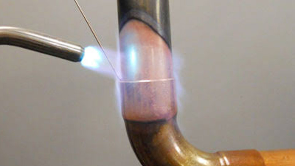
Photo by harrisproductsgroup
Flame Chemistry Decisions That Control Joint Quality
The oxy-acetylene flame must deliver enough energy to bring both the tube and fitting to brazing temperature without creating oxides that block wetting.
Neutral Versus Slightly Reducing Flame Selection
A neutral flame shows a sharp, well-defined inner cone with no secondary acetylene feather. This balance supplies the highest usable heat without excess free oxygen or free carbon.
Many copper-to-copper operators prefer a slightly reducing (carburizing) flame—characterized by a small secondary feather—because the excess acetylene atmosphere reduces surface oxides and wraps heat more evenly around the joint.
An oxidizing flame (hissing, short inner cone) forms black copper oxide that prevents filler flow and must be avoided. Light the acetylene first, then add oxygen until the feather just disappears for neutral, or leave a short feather for reducing conditions.
Regulator Pressures Matched to Tip and Pipe Size
Acetylene working pressure should stay between 4 and 7 psi for most copper work and must never exceed 15 psi. Oxygen typically runs 8–15 psi. For ¼–½ inch copper with a #1 or #2 tip, 8–12 psi oxygen and 4–6 psi acetylene produce a controllable neutral or soft reducing flame.
Larger ¾–1 inch tube often requires a #3 or #4 tip with oxygen raised to 12–15 psi and acetylene to 5–7 psi. Set pressures with the torch valves open so the gauges reflect dynamic flow. Excess pressure simply wastes gas and makes the flame harder to control on thin-wall tube.
Filler Metal Selection for Copper-to-Copper and Dissimilar Joints
The filler determines both mechanical performance and whether separate flux is required.
Phosphorus-Bearing BCuP Alloys for Copper-to-Copper
BCuP-2 (approximately 7 % phosphorus, no silver) and BCuP-5 (15 % silver, 5 % phosphorus) are the workhorses for copper-to-copper.
Phosphorus provides self-fluxing action on clean copper, eliminating the need for external flux. BCuP-5 offers a lower liquidus (around 1475 °F) and better ductility than silver-free grades, making it preferred for HVAC lines subject to vibration and thermal cycling.
Solidus temperatures for these alloys fall near 1190 °F, so the joint only needs to reach a dark cherry red for capillary flow. Apply the rod to the joint, not into the flame; the base metal must supply the heat that melts the filler.
Silver Alloys When Flux or Dissimilar Metals Are Required
When joining copper to brass, steel, or other alloys, switch to BAg-series fillers (15–45 % silver). These require a separate water-based brazing flux. Flux becomes fluid and clear at temperature, signaling that the joint is ready.
Higher-silver alloys also improve gap-filling ability when joint clearances exceed the ideal 0.001–0.005 inch range. Match the filler liquidus to the service temperature of the system; refrigeration lines commonly stay with BCuP-5 or 15 % silver for both economy and performance.
Visual Temperature Control and Heat Distribution
Copper conducts heat so rapidly that localized overheating is the most common cause of burned flux, annealed tube, and incomplete penetration.
Dark Cherry Red as the Practical Target
Most BCuP and common silver alloys flow reliably once the copper reaches a dull to dark cherry red, corresponding to roughly 1150–1300 °F. Bright orange or yellow indicates temperatures approaching or exceeding 1500 °F and risks melting the tube wall or creating excessive grain growth.
Watch the fitting more than the tube; the heavier wall of the fitting absorbs heat slower and must reach temperature first so capillary action pulls filler into the socket rather than outward.
Heating Sequence That Forces Capillary Fill
Begin heating the fitting on the side opposite the operator, then move the flame continuously around the joint in a circular or figure-eight pattern. Keep the inner cone ½–1 inch from the metal. Once both members show uniform color, touch the filler to the joint mouth.
If the filler balls up, the metal is still too cold; if it flows and disappears into the gap, temperature and cleanliness are correct. Continue feeding until a continuous fillet appears around the entire circumference. On vertical joints, heat slightly more on the lower side so gravity assists rather than opposes capillary flow.
Torch Tip Size and Heat Input Matching
Tip orifice size controls BTU delivery and therefore the time required to reach brazing temperature.
Small-Diameter Tube (⅛–½ Inch)
A #0, #1, or #2 tip supplies adequate heat without risk of blow-through. These tips pair with the lower pressure ranges listed earlier and allow precise control in tight mechanical rooms. On thin-wall ACR tubing the smaller tip also reduces the chance of annealing adjacent sections.
Larger Tube and Fittings (¾ Inch and Above)
Move to a #3, #4, or multi-orifice rosebud tip. The increased heat volume shortens the time the entire assembly spends at elevated temperature, limiting oxidation and softening. Rosebud tips distribute heat over a wider area and are especially useful when brazing near valves or compressor stubs that must stay cool.
Always verify manufacturer tip charts for the specific torch series; orifice diameters and recommended pressures vary between brands.
Surface Preparation and Joint Clearance Requirements
No amount of heat or filler compensates for contaminated or poorly fitted surfaces.
Mechanical Cleaning Standards
Abrasive clean the outside of the tube and the inside of the fitting to bright metal. Emery cloth or a dedicated tube brush removes the oxide layer that forms rapidly on copper. Avoid steel wool that can leave iron particles.
After cleaning, wipe with a clean cloth; residual oils from hands or cutting fluids create gas pockets and incomplete wetting. Assemble the joint immediately after cleaning so that atmospheric oxidation does not restart.
Clearance That Enables Capillary Action
Ideal radial clearance is 0.001–0.005 inch. Excessively tight fits prevent filler entry; loose fits allow the filler to run out before solidifying. Standard wrought copper fittings are manufactured to these tolerances when the tube is cut square and deburred.
Support the assembly so that the tube remains fully seated against the fitting stop during heating; movement opens gaps and produces voids.
Nitrogen Purge Practice for Closed Systems
Internal oxidation is invisible until the system fails under pressure or contaminates the refrigerant circuit.
Flow Rates and Timing
For HVAC and refrigeration lines, introduce dry nitrogen at 2–5 SCFH (or roughly 2–3 psi on a regulator with a flow meter) before heating begins and maintain flow until the joint cools below 400 °F.
The nitrogen displaces oxygen inside the tube, preventing formation of cupric oxide scale that later flakes into expansion valves or compressor screens.
Purge both directions when possible on long runs. The same purge is unnecessary for open plumbing systems that will be flushed with water.
Common Failure Modes Linked to Parameter Errors
Incomplete penetration, porosity, and overheating each map to specific process mistakes.
Incomplete Filler Penetration
Usually caused by insufficient joint temperature, dirty surfaces, or heating only the tube instead of the fitting. Sectioned joints show filler stopped short of the socket bottom. Correct by verifying uniform dark-cherry color on both members before applying rod and by maintaining continuous nitrogen flow where required.
Porosity and Oxide Inclusions
Result from an oxidizing flame, absence of nitrogen purge, or flux that has been burned by excessive heat. The joint appears sound externally but leaks under pressure test. Switch to neutral or slightly reducing flame chemistry and keep the flame moving so that no single area exceeds the flux activation range for more than a few seconds.
Selecting the correct tip size, pressure combination, and filler alloy for the specific tube diameter and service conditions produces joints that consistently pass pressure and vibration tests.
Advanced operators further refine results by measuring actual joint clearance with feeler gauges on critical assemblies and by recording the exact flame appearance and time-to-temperature for each pipe size they routinely encounter; those data become the shop standard that eliminates trial-and-error on every new installation.
FAQs
What temperature is needed for brazing copper with oxy acetylene?
Most BCuP fillers flow once the copper reaches a dark cherry red, approximately 1150–1300 °F. The base metal must stay well below its 1984 °F melting point.
Do I need flux when brazing copper to copper?
No. Phosphorus-bearing BCuP alloys are self-fluxing on clean copper. Flux is required only for copper-to-brass, copper-to-steel, or other dissimilar combinations.
What torch tip size works best for ½-inch copper?
A #1 or #2 tip with 8–12 psi oxygen and 4–6 psi acetylene supplies controllable heat without overheating thin-wall tube.
Why does nitrogen purge matter during copper brazing?
Nitrogen displaces oxygen inside the tube and prevents formation of internal copper oxide scale that later contaminates refrigerant circuits or causes leaks under pressure.