Setting up a TIG welder for aluminum often fails because the machine is left on DC settings that work for steel. The arc starts dirty, the tungsten balls up, and the weld puddle oxidizes before it ever flows.
Getting how to set up a TIG welder for aluminum right means switching to AC, dialing balance and frequency, choosing the correct tungsten, and matching gas flow to cup size.
These decisions control cleaning action, arc focus, and heat input. Incorrect polarity or balance leaves black soot or burns through thin sheet. Correct setup produces a shiny, controllable puddle that wets out cleanly. The difference appears in the first 10 seconds of arc time.
Image by riselaser
Selecting AC Output and Polarity for Aluminum
Aluminum requires alternating current because the oxide layer melts at a much higher temperature than the base metal. DC electrode negative provides deep penetration but no cleaning. DC electrode positive gives aggressive cleaning but overheats the tungsten.
AC alternates between both, delivering cleaning on the electrode-positive half-cycle and penetration on the electrode-negative half-cycle.
Why Balance Control Matters More Than Amperage
Balance (or AC balance) sets the percentage of time spent on electrode-negative versus electrode-positive. Most modern inverters default to 70 % EN / 30 % EP. Raising EP to 40–45 % increases oxide cleaning for dirty or cast aluminum.
Lowering EP to 20–25 % reduces tungsten wear and concentrates heat for thin sheet. Start at 30 % EP on clean 6061 plate. If the weld edges show gray residue, increase EP in 5 % steps until the puddle wets cleanly. Excessive EP causes the tungsten to ball excessively and wander.
Frequency Settings and Arc Behavior
AC frequency controls arc constriction. Older transformer machines run at 60 Hz and produce a wider, softer arc. Inverter machines allow 40–400 Hz adjustment. Higher frequency (150–250 Hz) narrows the arc cone, improves directional control, and reduces heat input into the surrounding metal. Lower frequency (60–80 Hz) widens the arc for better cleaning on castings or heavy oxide.
For 1/8-inch and thinner sheet, 120–180 Hz keeps the arc tight without excessive tungsten erosion. For thicker plate or fillet joints, 80–120 Hz improves puddle fluidity.
Choosing and Preparing the Tungsten Electrode
Tungsten selection directly affects arc stability and electrode life on AC aluminum. Pure tungsten forms a stable ball but erodes quickly under high amperage. 2 % lanthanated or 1.5 % lanthanated electrodes hold a sharper point longer and tolerate higher current density.
Recommended Diameters and Grind Angles
Match diameter to expected amperage:
- 1/16-inch (1.6 mm) for 30–90 A
- 3/32-inch (2.4 mm) for 70–150 A
- 1/8-inch (3.2 mm) for 120–250 A
Grind the tip to a truncated point with a 15–30° included angle for AC work. Leave a flat land approximately one-third of the electrode diameter. This land forms a controlled ball during welding and prevents the arc from dancing.
Grind longitudinally so any grinding marks run parallel to the electrode axis; circumferential marks create arc instability.
Balling Versus Pointed Geometry
On pure tungsten the tip will ball naturally under AC. On lanthanated electrodes the tip holds a sharper geometry and only forms a slight radius. A fully ball-shaped tip widens the arc and is preferred for heavy cleaning or wide beads.
A near-pointed tip with a small land concentrates the arc for precision joints and thin material. Re-grind when the land becomes irregular or the arc starts to wander.
Shielding Gas Selection and Flow Rate
Pure argon remains the standard shielding gas for aluminum TIG. Helium additions raise arc temperature and increase travel speed on thick sections, but pure argon provides better cleaning action and arc starting.
Flow Rates Matched to Cup Size
Gas flow must flood the weld zone without turbulence. Use these starting points:
- #4–#5 cup: 10–15 CFH
- #6–#7 cup: 15–20 CFH
- #8–#10 cup: 20–25 CFH
Increase flow 3–5 CFH when welding outdoors or in drafty shops. Excessive flow creates turbulence that pulls air into the shield and produces porosity. Post-flow time should run 8–12 seconds so the tungsten and weld pool cool under argon protection. Pre-flow of 0.5–1 second clears residual air from the cup before the arc starts.
Gas Lens Versus Standard Collet Body
A gas lens creates laminar flow and extends the effective shielding distance. This allows the tungsten to stick out farther (up to ½ inch beyond the cup) while still protecting the puddle. Standard collet bodies require shorter stick-out (⅛–¼ inch) and are more sensitive to torch angle.
For aluminum fillet and outside corner joints, a gas lens reduces the chance of atmospheric contamination when the torch is tilted.
Setting Amperage, Pulse, and Start Parameters
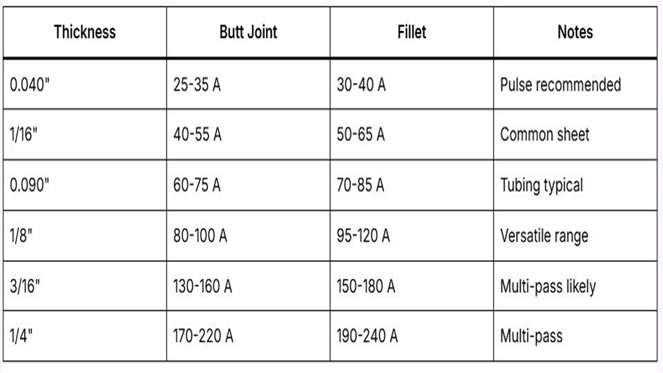
Amperage determines heat input. A practical rule is 1 amp per 0.001 inch of thickness for butt joints in the flat position. Adjust downward 10–15 % for thin sheet or upward for fillet welds and heavy sections.
Establishing Working Amperage Ranges
Approximate starting points for 6061 aluminum:
- 0.040-inch sheet: 40–60 A
- 1/16-inch: 60–90 A
- 1/8-inch: 110–140 A
- 1/4-inch: 180–220 A
These values assume AC, clean material, and a 3/32-inch tungsten. Increase amperage if the puddle fails to form within two seconds. Decrease if the edges undercut or the tungsten melts back excessively. Foot-pedal control allows real-time adjustment; set the machine maximum 20–30 % higher than the expected working current so the pedal has range.
Pulse Settings for Heat Control
Pulse is optional but useful on thin aluminum or out-of-position work. Typical settings:
- Peak current: 120–150 % of average welding current
- Background current: 30–50 % of peak
- Pulse frequency: 1–3 Hz for visible pulsing or 40–100 Hz for smoother heat averaging
- Pulse width (on time): 40–60 %
Low-frequency pulse produces distinct ripple and helps the operator track travel speed. High-frequency pulse smooths the bead and reduces overall heat input without changing the average amperage much.
Torch Configuration and Stick-Out
Torch angle, cup selection, and electrode stick-out influence gas coverage and arc focus.
Cup Size Versus Joint Access
Larger cups improve gas coverage on open joints but restrict access in tight corners. A #7 or #8 gas-lens cup covers most flat and horizontal aluminum work. Switch to a #5 or #6 for fillet welds inside corners or when the torch must be held nearly vertical. Ceramic cups are standard; glass cups allow better visibility but cost more and break more easily.
Stick-Out and Arc Length
Maintain electrode stick-out between ⅛ and ⅜ inch beyond the cup. Longer stick-out is possible with a gas lens. Arc length should stay short—roughly equal to the electrode diameter. Longer arcs increase voltage, widen the bead, and raise the risk of porosity. Keep the torch nearly vertical (0–15° travel angle) so the gas column remains centered over the puddle.
Material Preparation That Affects Setup Success
Aluminum oxide reforms within minutes of cleaning. Mechanical removal and chemical wipe-down are required immediately before welding.
Cleaning Sequence and Timing
- Remove mill scale or heavy oxide with a dedicated stainless-steel wire brush used only on aluminum.
- Wipe with acetone or isopropyl alcohol to remove oils.
- Avoid touching the cleaned surface with bare hands.
- Weld within 15–30 minutes.
Wire-brushing after solvent cleaning recontaminates the surface with residual oils. Always brush first, then solvent-wipe. For thick plate, a light stainless-steel rotary brush or carbide burr can open the surface, but the final pass must still be a clean hand brush.
Joint Fit-Up and Backing Considerations
Tight fit-up reduces the amperage needed and improves heat transfer. Gaps larger than 1/16 inch require higher current and increase the chance of burn-through on thin sheet.
Copper or aluminum backing bars help support the root on butt joints and dissipate heat. Avoid steel backing; it can contaminate the aluminum if the root penetrates through.
Machine Checklist Before Striking an Arc
Run through these settings in order every time the machine is switched from steel to aluminum:
- Process: TIG / GTAW
- Polarity: AC
- Amperage range set 20–30 % above expected working current
- AC balance: 25–35 % EP
- AC frequency: 100–180 Hz
- High-frequency start: continuous
- Pre-flow: 0.5–1 s
- Post-flow: 8–12 s
- Gas: pure argon, flow matched to cup
- Tungsten: correctly sized, ground, and installed
Confirm the foot pedal or fingertip remote is calibrated and responsive. A sticky pedal causes over-amperage spikes that melt the tungsten or burn through the plate.
Troubleshooting Setup Problems That Appear Immediately
Most aluminum TIG defects trace back to setup rather than technique.
Black Soot or Dirty Puddle
Increase EP balance 5–10 %. Verify argon purity and flow. Check for leaks in the torch hose or connections. Confirm the tungsten is clean and free of steel contamination.
Tungsten Melting or Balling Excessively
Reduce EP percentage. Lower maximum amperage. Shorten stick-out. Switch to a larger-diameter lanthanated electrode if current demand exceeds the electrode rating.
Porosity in the Bead
Raise gas flow 3–5 CFH and lengthen post-flow. Inspect for drafts. Confirm the aluminum was cleaned immediately before welding. Check for moisture in the argon line or a contaminated gas lens screen.
Arc Wandering or Hard Starting
Re-grind the tungsten. Increase high-frequency intensity if the machine allows. Verify AC frequency is not set extremely high (above 250 Hz can make starting more difficult on some machines). Ensure the work clamp has clean metal-to-metal contact.
Advanced Setup Adjustments for Specific Alloys and Positions
6061 and 5052 respond well to the ranges listed earlier. Cast aluminum (A356, 356) often needs higher EP balance (35–45 %) and slightly higher amperage because of porosity and thicker oxide. 7000-series alloys are more crack-sensitive; keep heat input low with pulsed current and avoid over-welding.
Out-of-position aluminum benefits from higher frequency (150–250 Hz) and modest pulse to control the puddle. Vertical-up requires a narrower arc and lower average amperage than flat welding.
Overhead work demands the shortest possible arc length and precise balance so the cleaning action does not spray molten metal downward.
Decision-Making Summary for Reliable Aluminum TIG Setup
Correct polarity, balance, frequency, tungsten, and gas flow form the foundation. Start with AC at 30 % EP, 120–150 Hz, pure argon at 15–20 CFH, and a properly prepared lanthanated electrode sized to the current. Adjust only one variable at a time while watching the puddle.
The setup is correct when the oxide clears within the first second, the tungsten holds a stable geometry, and the puddle wets the base metal without undercutting or soot.
Once those conditions appear, travel speed and filler addition become the remaining variables. Experienced operators treat the machine settings as fixed for a given thickness and alloy, then vary only pedal pressure and torch angle to control the final bead shape.
FAQ
What amperage should I use for 1/8-inch aluminum TIG welding?
Start between 110–140 A on AC with a 3/32-inch lanthanated electrode. Increase if the puddle forms slowly; decrease if edges undercut. Foot-pedal control lets you fine-tune in real time.
Do I need pure tungsten or lanthanated for aluminum?
Lanthanated (1.5 % or 2 %) holds a sharper point longer and tolerates higher current. Pure tungsten balls more readily and erodes faster under continuous AC. Most modern setups prefer lanthanated.
Why does my aluminum weld look dirty even with argon?
Balance is usually set too low on electrode-positive. Raise EP percentage 5–10 %. Also verify the material was cleaned immediately before welding and that gas flow matches cup size without turbulence.
Can I TIG weld aluminum on DC?
DC electrode positive provides cleaning but overheats the tungsten rapidly. DC electrode negative gives penetration with no cleaning. AC remains the practical and standard choice for production aluminum TIG work.