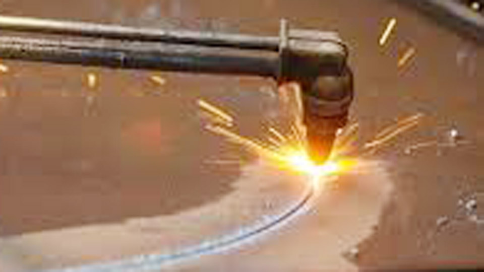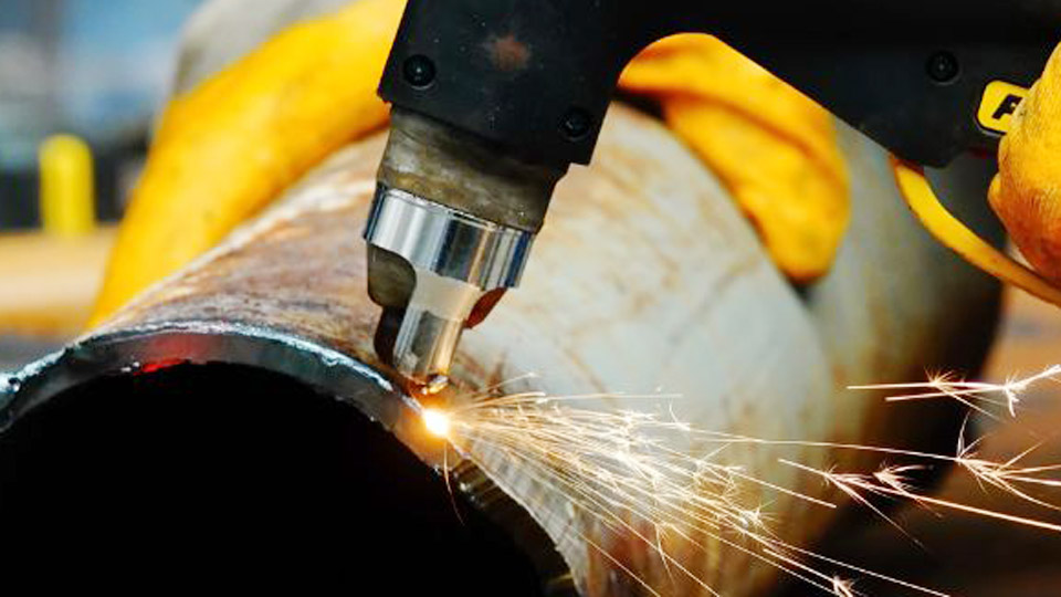
Most shops already own a heavy transformer stick welder that sits idle between repair jobs, yet clean plate cutting still requires either an angle grinder marathon or a $500–$1,200 commercial plasma unit.
The question of how to make a plasma cutter from an arc welder therefore appears frequently: can the existing power source be modified to deliver a constricted, high-velocity plasma jet instead of a welding arc? The answer involves more than adding a torch and air.
Plasma cutting demands open-circuit voltages of 200–400 VDC, sustained arc voltages of 90–150 V, precise gas timing, and matched consumables—characteristics that a standard 50–80 V stick machine does not provide.
Understanding the exact electrical and pneumatic gaps, and the modifications required to close them, determines whether conversion is technically viable or whether a dedicated cutter remains the safer, more productive choice.
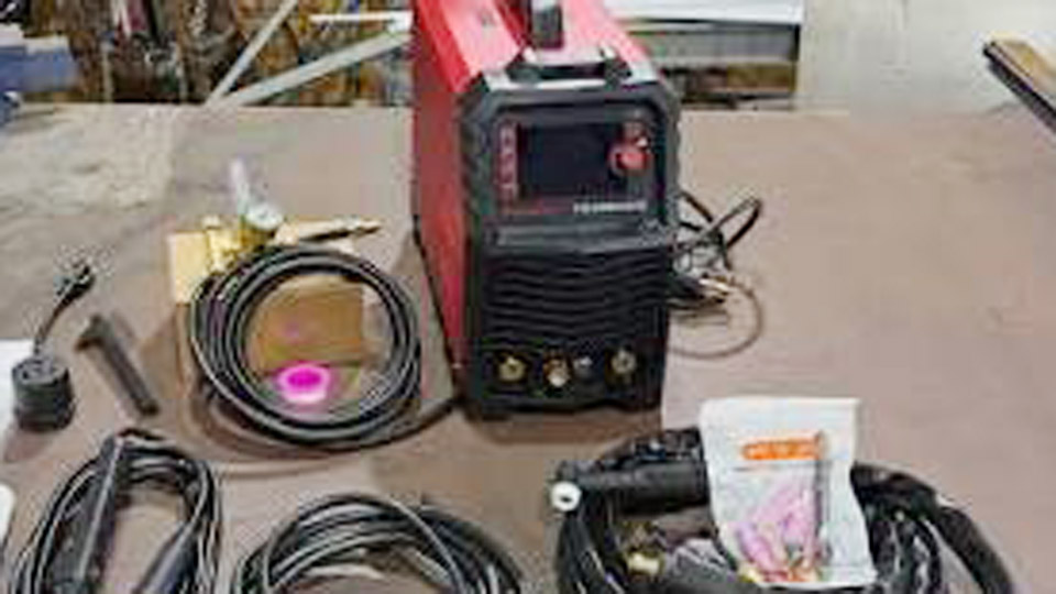
Image by ig/sewingwithfirewelding
Why Stick Welders and Plasma Cutters Operate on Different Electrical Curves
A stick welder is engineered for constant-current output at low voltage. Under load the arc runs at 20–35 V while open-circuit voltage stays between 50 and 80 V.
Plasma cutting ionizes a gas column through a nozzle orifice and maintains that column across a standoff gap; this requires far higher voltage to overcome the resistance of the gas before the main arc transfers to the workpiece.
Open-Circuit Voltage Requirements for Plasma
Commercial plasma supplies typically deliver 250–350 VDC open-circuit. After the arc transfers, voltage drops to 90–130 V depending on nozzle size and air pressure.
A transformer welder’s secondary winding of 20–40 VAC, once full-wave rectified and capacitively filtered, can reach 280–340 VDC. Without that voltage headroom the plasma column extinguishes on thicker material or when the torch is lifted even slightly.
Current Density and Power Balance
DIY plasma systems usually run 30–60 A at the higher arc voltage. Power (volts × amps) remains comparable to a 150–200 A stick setting, yet the volt-amp curve must stay stiff. Transformer machines with substantial leakage inductance handle this load better than most inverters, whose control boards and IGBTs often fold back or overheat under continuous high-voltage duty.
Core Power-Supply Modifications Needed for Conversion
Only older transformer-based “buzz-box” or engine-driven welders rated 180 A or higher are practical candidates. Inverter machines rarely tolerate the reflected high-voltage spikes or altered thermal loading without extensive internal rewiring.
Rectification, Capacitance, and Current Limiting
A 200–300 A, 600–1000 V stud-mount bridge rectifier converts the welder secondary to DC. Parallel a bank of 2000–5000 µF capacitors rated 400–450 V to supply the surge current required for piercing and to stabilize voltage under load.
A series 5–10 Ω, 500–1000 W resistor (nichrome or paralleled water-heater elements) prevents transformer saturation and limits peak current to the 40–80 A range the torch can safely handle. Bleed resistors of 100 kΩ across each capacitor discharge stored energy after shutdown.
High-Frequency Pilot-Arc Starter
A flyback transformer scavenged from a CRT monitor or a high-voltage ignition-coil driver produces 20–50 kV at 15–30 kHz. This voltage is capacitively coupled into the torch electrode lead to ionize the air gap and establish a pilot arc.
Once main cutting current exceeds approximately 10–15 A, a reed switch or current transformer disables the high-frequency circuit so it does not continue to stress insulation.
Torch Selection, Air Delivery, and Consumable Matching
The electrical conversion is useless without a torch designed for constricted plasma flow and a clean, dry air supply that matches the amperage range.
Compatible Torch Ratings and Orifice Sizes
A PT-31-style or equivalent 40–60 A air-cooled torch is the most common choice for these conversions. Nozzle orifices of 0.035–0.045 inch pair with 30–55 A cutting currents. Electrode and nozzle life typically ranges from 50 to 150 pierces when air is properly filtered; moisture or oil contamination shortens that life dramatically.
Air Pressure, Flow, and Filtration Targets
Shop compressors should supply 90–120 PSI at the tank, regulated to 25–40 PSI at the torch for most DIY 30–60 A systems. Flow requirements fall in the 4–8 CFM range.
A moisture separator followed by a coalescing filter is mandatory; water droplets inside the nozzle destroy the electrode in fewer than ten starts. A solenoid valve triggered by the torch switch ensures air flows only during cutting and provides post-flow cooling.
Realistic Cutting Capacity and Duty-Cycle Limits
A properly executed conversion of a 200 A transformer welder routinely produces clean cuts in ¼-inch mild steel at 40–50 A and 12–18 inches per minute. Three-eighths-inch plate is possible at 55–65 A with slower travel and more dross.
Half-inch material pushes the system near its thermal and voltage limits and usually yields only severance cuts rather than production-quality edges.
Amperage, Pressure, and Speed Relationships
Typical starting parameters for mild steel:
| Thickness | Amps | Air PSI | Travel Speed (IPM) | Nozzle Orifice |
|---|---|---|---|---|
| ⅛ inch | 30–35 | 25–30 | 18–25 | 0.035 |
| ¼ inch | 40–50 | 30–35 | 12–18 | 0.040 |
| ⅜ inch | 55–65 | 35–40 | 8–12 | 0.045 |
Pierce at roughly 1.5 times cutting amperage with increased standoff, then drop to ⅛–3/16 inch standoff for the cut. Stainless and aluminum require slightly higher current and produce more bottom-edge dross that must be cleaned.
Thermal Constraints on Continuous Duty
The limiting resistor dissipates 1–2 kW and the welder itself is running outside its original design envelope. Expect 40–60 % duty cycle at 50 A before thermal shutdown. Auxiliary cooling fans on the rectifier, capacitors, and resistor extend usable run time but do not turn the system into a continuous-duty industrial cutter.
Safety, Isolation, and Practical Decision Points
High-voltage DC at 280–340 V open-circuit is lethal. Capacitors retain charge long after the machine is switched off. Homemade enclosures rarely provide the creepage distances, interlocks, or fault protection found in listed commercial equipment. Electromagnetic interference from the high-frequency starter can disrupt nearby electronics and control circuits.
When Conversion Is Technically Feasible
Conversion makes sense only when three conditions are met simultaneously: the builder has documented experience with high-voltage DC power electronics, a transformer welder with accessible secondary terminals and adequate cooling is already on hand, and the intended duty is intermittent light fabrication rather than production cutting.
Even then, the finished unit should be treated as an experimental tool, never as a substitute for a certified plasma cutter in a professional or code-required environment.
When a Dedicated Plasma Cutter Is the Correct Choice
Entry-level 40–55 A inverter plasma cutters now cost less than the cumulative parts, time, and risk of a full conversion. They include matched torches, proper thermal protection, pilot-arc or blow-back starting, and tested insulation systems.
For any shop that cuts metal more than a few hours per month, the commercial unit delivers higher productivity, longer consumable life, and far lower liability.
Wrapping Up
A converted transformer welder can produce functional plasma cuts on ¼-inch plate when the voltage, current-limiting, and air systems are correctly matched. The engineering differences between stick welding and plasma cutting, however, are large enough that most users achieve better results and lower risk by purchasing a purpose-built machine.
Advanced builders who complete a stable conversion often add primary-side phase-angle control so amperage can be varied continuously without changing the series resistor—an upgrade that turns a fixed-output experiment into a more versatile shop tool while still operating within the thermal limits of the original transformer.
FAQs
Can any stick welder be converted into a plasma cutter?
Only older transformer machines rated 180 A or higher with accessible secondary windings are practical. Inverter welders generally lack the magnetic mass and voltage tolerance required and are not recommended for conversion.
What open-circuit voltage is needed for plasma cutting?
Commercial and successful DIY systems operate at 200–400 VDC open-circuit. A typical 40 VAC welder secondary rectifies and filters to approximately 280–340 VDC, which is the minimum useful range.
How thick can a DIY plasma conversion cut cleanly?
Most well-executed 40–60 A conversions produce clean cuts in ¼-inch mild steel and acceptable severance cuts in ⅜-inch plate. Half-inch material is usually limited to rough severance.
Is the simple carbon-electrode and air-blast method true plasma cutting?
No. That technique is a form of air-carbon-arc cutting. It produces a broader, rougher kerf and does not create a constricted plasma jet.