
Selecting the correct wire feed speed is one of the most important factors in producing consistent MIG welds. A Wire Feed Speed Calculator and Formula helps eliminate guesswork by estimating the proper wire feed rate based on material thickness, wire diameter, welding current, and other key variables.
Incorrect settings can lead to poor penetration, excessive spatter, lack of fusion, burn-through, or an unstable arc that reduces weld quality and increases rework.
Whether you’re welding mild steel, stainless steel, or aluminum, understanding how wire feed speed is calculated allows you to fine-tune your machine for better arc performance and deposition efficiency.
By learning the underlying formula and using a reliable calculator, you can make faster setup adjustments, improve weld consistency, and achieve stronger, cleaner welds across a wide range of fabrication and repair projects.
Wire Feed Speed Calculator
Understanding Wire Feed Speed in MIG Welding
Wire feed speed determines how quickly filler wire enters the weld pool, directly influencing heat input and metal deposition.
Core Role of Wire Feed Speed
In constant voltage MIG systems, WFS primarily sets the welding amperage. Higher speeds increase current draw as the arc consumes more wire, raising penetration and deposition.
Lower speeds reduce amperage for thinner materials or positional welding. Typical ranges run from 100 IPM for thin sheet to over 500 IPM for heavy plate.
WFS interacts with voltage to balance arc length. Voltage controls arc length and bead width; WFS controls current and wire melt rate. Proper synchronization produces a stable, crackling arc with minimal spatter.
Relationship Between Wire Feed Speed and Amperage
A practical rule of thumb for .030-inch solid wire: multiply desired amperage by approximately 2 to estimate IPM. For 150 amps, target around 300 IPM as a starting point.
This multiplier varies slightly by wire diameter and composition—smaller wires need higher multipliers per amp due to faster burn-off.
For .035-inch wire, the factor drops closer to 1.6–1.8 IPM per amp. Always verify with machine-specific charts or test runs, as actual amperage depends on stickout, gas type, and polarity.
Measuring and Verifying Actual Wire Feed Speed
To measure WFS, disable the arc (trigger without welding or use a test mode) and feed wire for 6 seconds. Multiply the length by 10 for IPM. Repeat several times for consistency, as tension, liner condition, and drive roll pressure affect delivery. This verification step eliminates discrepancies between dial settings and real output.
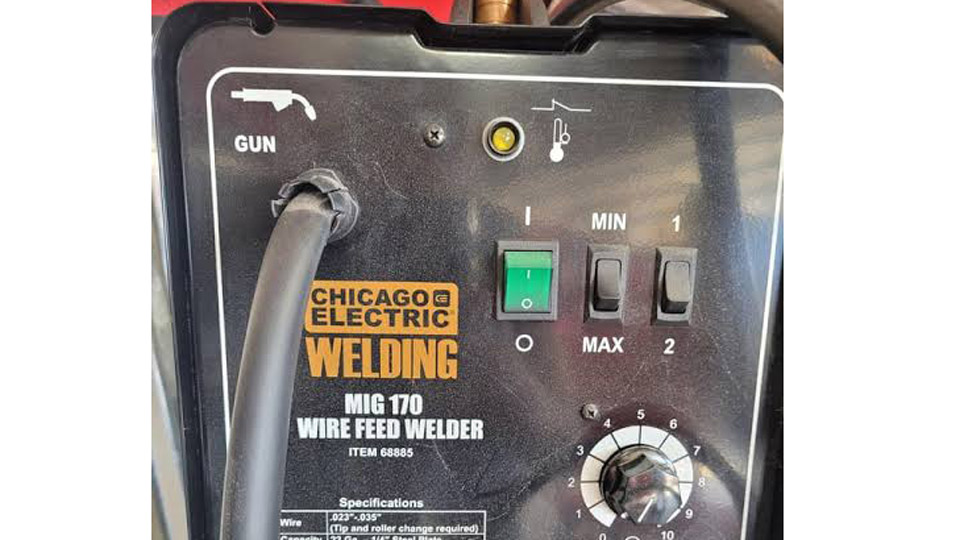
Image by r/Welding
The Basic Wire Feed Speed Formula
Accurate calculation starts with material thickness and wire diameter.
Core Formula for Wire Feed Speed
WFS (IPM) = Material Thickness (in thousandths of an inch) × Burn-Off Factor
Common burn-off factors:
- .023″ / .024″ wire: 3.5
- .030″ wire: 2.0–2.2
- .035″ wire: 1.6–1.8
- .045″ wire: 1.2–1.4
For 1/8-inch (0.125″) steel with .030″ wire: 125 × 2.0 = 250 IPM base. Adjust upward for gaps or downward for fillet welds.
This formula provides a reliable starting point across mild steel applications. Fine-tune by 10–20% based on observed puddle behavior.
Examples Across Wire Diameters and Thicknesses
For 16-gauge (0.060″) steel with .023″ wire: 60 × 3.5 ≈ 210 IPM. This keeps heat low to prevent distortion.
On 1/4-inch plate with .035″ wire: 250 × 1.6 ≈ 400 IPM for good penetration in flat position.
For .045″ wire on 3/8-inch material: 375 × 1.2 ≈ 450 IPM. These values align with deposition needs while matching typical voltage settings of 18–22V.
Always cross-reference with deposition rate goals. Excessive WFS without matching travel speed creates wide, shallow beads.
Wire Feed Speed Charts and Practical Calculators
Reference charts accelerate setup while formulas allow customization.
Settings by Wire Diameter and Thickness
0.023–0.024″ Wire (Thin Materials):
- 24–20 ga: 100–150 IPM
- 18–16 ga: 150–200 IPM
- Voltage: 14–17V
0.030″ Wire (General Purpose):
- 14–12 ga: 175–225 IPM
- 1/8″: 225–300 IPM
- 3/16″: 280–350 IPM
- Voltage: 16–20V
0.035″ Wire (Medium Thickness):
- 1/8″: 250–325 IPM
- 1/4″: 300–400 IPM
- 3/8″: 350–450 IPM
- Voltage: 17–22V
0.045″ Wire (Heavy Fabrication):
- 1/4″: 350–450 IPM
- 3/8″+: 450–600+ IPM
- Voltage: 20–26V
These ranges assume 75/25 Ar/CO2 gas and short-circuit or globular transfer. Spray transfer requires higher WFS and voltage.
Online and Manual Calculator Approaches
Input thickness, wire diameter, material type, and gas into a calculator for instant recommendations. Manual versions use the burn-off formula plus modifiers: add 10–15% for out-of-position or root passes; subtract for weave techniques. Test on scrap to dial in exact settings for your machine and technique.
Key Factors Affecting Optimal Wire Feed Speed
Multiple variables require adjustment beyond basic formulas.
Material Type, Thickness, and Joint Configuration
Thicker materials demand higher WFS for penetration. Aluminum requires 20–30% higher speeds than steel due to higher thermal conductivity and different wire properties. Stainless steel often needs slight reductions to control heat input and prevent sensitization.
Butt joints with gaps benefit from 10–20% higher WFS to bridge voids. Fillets on thick plate perform best at moderate speeds with stringer beads. Lap joints on thin sheet favor lower settings to minimize distortion.
Shielding Gas Influence on Settings
Pure CO2 increases penetration but may require 5–10% higher WFS for stability compared to 75/25 mixes. Argon-rich mixes support spray transfer at higher WFS with smoother arcs and less spatter. Flow rates of 15–25 CFH pair with these adjustments—too low causes porosity regardless of WFS.
Helium blends for aluminum further increase required WFS due to hotter arcs.
Welding Position and Technique Variables
Flat and horizontal positions tolerate higher WFS. Vertical-up demands 15–25% reduction to control puddle. Overhead requires even lower speeds plus shorter stickout (3/8–1/2 inch). Stickout length affects resistance: longer stickout (beyond 3/4 inch) effectively lowers amperage, requiring WFS compensation upward.
Travel speed must match deposition—too slow with high WFS causes excessive buildup; too fast yields lack of fusion.
Advanced Calculations: Deposition Rate and Travel Speed Integration
Link WFS to productivity metrics for professional results.
Deposition Rate Formula
Deposition Rate (lb/hr) = 13.1 × (Wire Diameter in inches)² × WFS (IPM) × Efficiency
Efficiency: 1.0 for solid wire, 0.85 for flux-cored.
Example: 0.045″ solid wire at 400 IPM → 13.1 × (0.045)² × 400 × 1.0 ≈ 10.6 lb/hr. This informs labor estimates and pass planning on large projects.
Flux-cored wires achieve higher deposition at similar WFS due to larger diameters and different transfer characteristics.
Synchronizing WFS with Travel Speed
Optimal travel speed approximates deposition needs. For 1/4-inch fillet: aim for 8–12 IPM travel with appropriate WFS. Calculate required deposition per pass, then set WFS accordingly. Weave techniques allow slightly lower WFS per pass but increase total time.
Monitor heat input (kJ/in) = (Amps × Volts × 60) / Travel Speed (IPM) for critical applications like pressure vessels or high-strength steels.
Troubleshooting and Fine-Tuning Wire Feed Speed
Recognize symptoms and adjust systematically.
High WFS Symptoms and Corrections
Excessive spatter, burn-through, or undercut signals overly high WFS. Reduce by 10–20% increments while monitoring arc sound and bead profile. Increase voltage slightly to maintain arc length if stubbing occurs. Check drive rolls, liner, and contact tip for restrictions before changing parameters.
Low WFS Symptoms and Corrections
Convex beads, poor fusion, or unstable arc indicate insufficient WFS. Increase gradually while watching for puddle control. On thin materials, pair increases with faster travel or lower voltage.
Machine and Consumable Interactions
Inconsistent feed points to tension issues, worn parts, or wrong drive rolls (use V-groove for solid wire, U-groove for softer alloys). Digital machines with synergic settings simplify this but still benefit from manual override knowledge for edge cases.
Real-World Applications Across Welding Projects
Apply these principles to specific scenarios for reliable outcomes.
Automotive repair on thin body panels uses .023″ or .030″ wire at 150–250 IPM with short-circuit transfer for minimal distortion. Structural steel fabrication leans on .035″ or .045″ at 300–500 IPM for efficiency. Pipe welding in vertical positions prioritizes precise WFS control for root and cap passes.
Hobbyists benefit from preset charts, while professionals combine formulas with experience for rapid setup on varied jobs. Always run test coupons matching the exact material, thickness, and position.
Performance Takeaway
Consistent mastery of the wire feed speed calculator and formula separates adequate welds from high-quality, efficient ones. The best welders treat WFS as the primary control variable, adjusting voltage and travel speed around it for optimal arc characteristics and mechanical properties.
In demanding applications, this approach—combined with proper consumable selection—delivers superior fusion, reduced defects, and faster completion times.
FAQ
How do I calculate wire feed speed without a chart?
Use the formula WFS (IPM) = Thickness (thousandths) × Burn-Off Factor for your wire diameter. Verify with a 6-second feed test and fine-tune on scrap matching your job.
Does shielding gas change the ideal wire feed speed?
Yes. CO2-rich mixes often need slightly higher WFS for stability, while argon-heavy mixes support higher speeds in spray transfer with less spatter. Adjust 5–15% when changing gases.
What wire feed speed is best for vertical MIG welding?
Reduce standard flat-position settings by 15–25%. Prioritize shorter stickout and controlled travel speed to manage the puddle.
How does wire feed speed relate to amperage on my machine?
WFS directly sets amperage in most MIG setups. Use manufacturer multipliers (e.g., ~2 IPM per amp for .030″ wire) as starting points, then confirm with an ammeter if available.


