Shop owners and fabricators regularly face the same costly mix-up: buying or operating one machine for a task it cannot perform. A plasma cutter removes metal; a welder joins it. Confusing the two produces incomplete cuts, weak joints, damaged consumables, and wasted project time.
Understanding what’s the difference between a plasma cutter and a welder determines whether plate is profiled cleanly before assembly or whether two members fuse into a load-bearing structure.
The distinction is not cosmetic—it is fundamental to process physics, power delivery, gas flow, and final part integrity. Selecting the wrong tool forces compensatory techniques that never match the correct process performance.
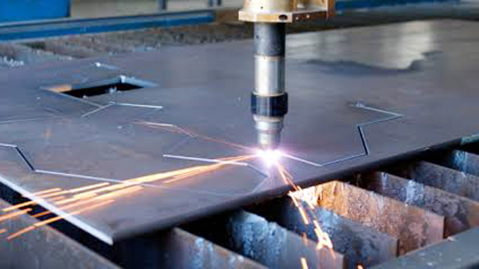
Image by wileymetal
Core Process Difference – Removal Versus Fusion
The fundamental separation lies in what each arc is engineered to do with molten metal.
How the Plasma Arc Creates a Kerf
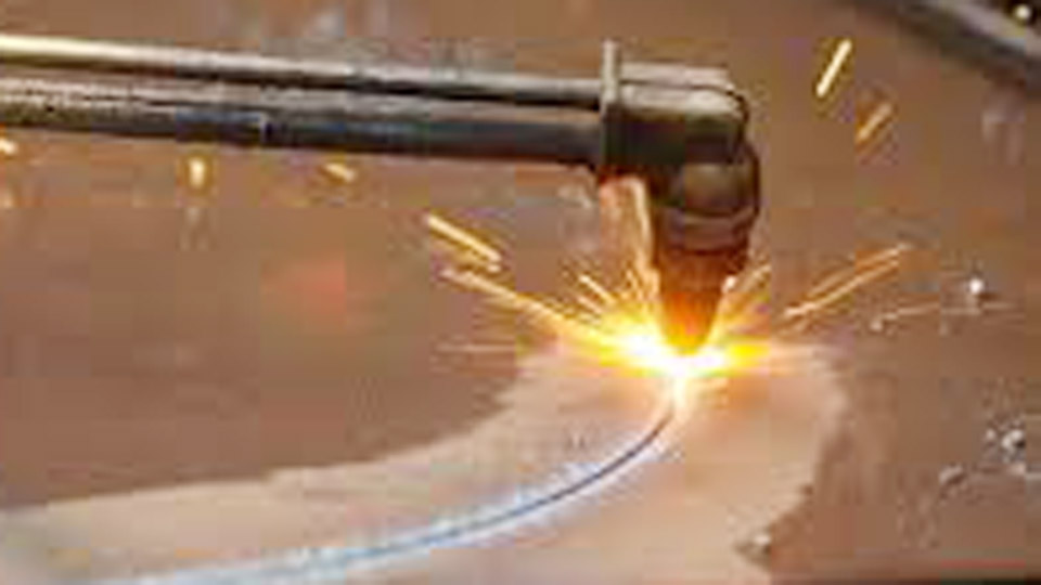
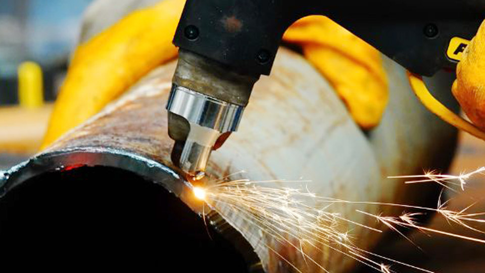
A plasma cutter forces an electric arc through a constricted nozzle while a high-velocity stream of gas (usually compressed air) ionizes into plasma. Temperatures exceed 20,000 °C in the arc column. The plasma melts a narrow path through the conductive workpiece, and the gas jet simultaneously ejects the molten metal from the kerf.
The result is a clean separation rather than a fused joint. Torch height, travel speed, and amperage control kerf width, bevel angle, and dross adhesion.
On mild steel a 40–45 A air-plasma process typically produces a quality cut on ¼-inch plate at moderate speeds; higher amperage units extend clean capacity to ½-inch or more while maintaining acceptable edge quality.
How Welding Processes Form a Joint
Welding processes generate an arc that melts base metal (and usually filler) so the molten pools coalesce and solidify into a continuous metallurgical bond. Stick (SMAW) uses a flux-coated consumable electrode. MIG (GMAW) feeds continuous solid or flux-cored wire under shielding gas.
TIG (GTAW) maintains a non-consumable tungsten electrode under inert gas while filler is added separately. In every case the goal is fusion and controlled solidification, not ejection of metal.
Heat input, travel speed, and filler addition are balanced to achieve penetration, bead profile, and mechanical properties required by the joint design.
Equipment and Utility Requirements That Separate Them
Hardware differences make interchangeability impractical outside specialized multi-process platforms.
Power Source and Output Characteristics
Plasma power sources regulate cutting current and coordinate pilot-arc transfer, gas timing, and post-flow cooling. Many units operate on constant-current characteristics optimized for the constrained plasma arc. Welding power sources differ by process: constant-voltage output suits MIG wire feed, while constant-current output suits stick and TIG.
A standard welding machine lacks the high-frequency or contact-start circuitry, gas sequencing, and torch protection interlocks required for stable plasma cutting. Attempting to force a welding output into a cutting role produces unstable arcs, rapid consumable failure, and incomplete severance.
Gas and Air Systems
Plasma cutting relies on a continuous, clean, dry compressed-air supply (typically 60–90 psi and adequate CFM) or specialty gases such as nitrogen or argon-hydrogen mixes for stainless and aluminum. The gas both forms the plasma and expels molten metal. Welding gas systems serve a different purpose.
MIG and TIG use shielding gases (argon, CO₂ mixes, helium) solely to protect the weld pool from atmospheric contamination. Stick electrodes generate their own shielding from flux decomposition and require no external gas cylinder.
Air quality requirements also diverge: moisture or oil in plasma air lines destroys electrodes and nozzles within minutes, while welding shielding gas must remain pure but does not experience the same high-velocity nozzle constraints.
Consumables and Torch Design
Plasma torches contain matched sets of electrode, nozzle (or tip), swirl ring or diffuser, shield, and retaining cap. These parts are process-specific and wear according to amperage, pierce frequency, and air quality.
Welding consumables are entirely different: stick electrodes of defined AWS classifications, MIG contact tips and liners sized to wire diameter, or TIG tungsten electrodes ground to specific geometries.
Torch geometry itself differs. Plasma nozzles constrict the arc and accelerate the gas jet; welding torches focus on stable arc length, gas coverage, and filler delivery.
Material Compatibility and Thickness Limits in Practice
Both tools work primarily on electrically conductive metals, yet their practical thickness windows and edge results diverge sharply.
What Plasma Cutters Handle Cleanly
Plasma cutting is limited to conductive materials—mild steel, stainless steel, aluminum, copper, brass, and similar alloys. Non-conductive materials cannot sustain the transferred arc. Thickness capacity scales with amperage and process.
Entry-level 30–40 A units clean-cut roughly ⅜-inch mild steel and sever up to ½-inch. 60 A machines commonly deliver quality cuts on ½-inch and severance near ¾-inch. Industrial systems rated 80–125 A and higher extend clean capacity toward 1-inch and beyond.
Aluminum and stainless generally require slightly higher energy or adjusted speeds relative to mild steel of the same thickness because of thermal conductivity and oxide behavior. Edge quality is measured by kerf width, angularity, dross adhesion, and heat-affected zone depth.
Welding Process Thickness Ranges
Welding processes cover a broader thickness spectrum when the correct process and parameters are chosen. Short-circuit MIG handles sheet-metal gauges effectively. Spray-transfer MIG and flux-cored processes deposit metal efficiently on medium plate.
Stick electrodes excel on structural sections from ⅛-inch upward and remain practical on heavy plate. TIG provides precise control on thin gauge through moderate thickness where appearance and metallurgy matter.
Multi-pass techniques allow welders to join material far thicker than any portable plasma cutter can sever in a single pass. The limiting factor becomes joint design, interpass temperature, and mechanical properties rather than simple penetration of a cutting jet.
When the Job Calls for Cutting Instead of Welding
Correct process selection begins with the required end state of the metal.
Profile Cutting, Piercing, and Trimming Decisions
Plasma is the efficient choice when material must be separated, shaped, or pierced. Bracket profiles, notches, holes, demolition cuts, and preparation of plate for later welding all fall into this category. Mechanized or CNC plasma tables further improve repeatability and edge consistency on production runs.
Plasma gouging attachments can remove weld metal or defects, providing a controlled material-removal function that pure welding processes cannot match. Travel speeds on thin plate often exceed what an operator can sustain with a hand torch for long distances, making plasma faster for extensive cutting.
Joint Preparation Versus Final Assembly
Plasma-cut edges frequently serve as the starting point for welded fabrication. A square or lightly beveled plasma edge can be ground and then welded. However, the plasma process itself does not create the joint. Once parts are positioned, the welding process supplies the fusion, filler metal, and required mechanical properties.
Using a welder to “cut” by melting through plate produces wide, irregular edges, excessive heat input, and heavy cleanup. The reverse—attempting to join parts with a plasma torch—simply ejects metal instead of allowing pools to coalesce.
Cost, Speed, and Skill Factors That Drive the Choice
Operating economics and learning curves reinforce the functional split.
Consumable and Utility Operating Costs
Plasma consumables (electrode and nozzle sets) wear with every pierce and linear inch of cut; costs rise with higher amperage and dirty air. Air compressor electricity and maintenance add ongoing expense.
Welding consumable costs vary: stick electrodes are inexpensive per joint, MIG wire is economical for long seams, and TIG tungsten lasts longer but shielding gas and filler rods accumulate cost on precision work.
Duty-cycle limits also differ. Many hobby plasma units and welders share similar thermal limits, yet production plasma systems often emphasize continuous cutting capacity while welding machines emphasize sustained deposition rates.
Learning Curve and Process Control Variables
Plasma cutting has a relatively short learning curve for basic straight and curved cuts once torch height, speed, and amperage are matched to thickness. Edge quality feedback (spark stream angle, dross color, kerf uniformity) is immediate.
Welding processes demand simultaneous control of arc length, travel speed, torch or electrode angle, and filler addition.
TIG presents the steepest skill requirement; MIG is more forgiving for beginners; stick requires practice in arc starting and slag management. Operators who master both tools still treat them as sequential rather than interchangeable steps in fabrication.
Multi-Process Machines and Specialized Overlaps
Some platforms combine welding and plasma capability in one chassis. These units share a power source but still require dedicated torch packages, correct polarity or process selection, and appropriate gas or air connections.
Plasma arc welding exists as a distinct joining process that uses a constricted plasma arc to form a weld pool rather than a cutting jet; it is not the same as a standard plasma cutter.
Carbon-arc cutting or gouging with a stick welder can remove metal roughly, yet it produces wider, less controlled results and higher heat input than purpose-built plasma. None of these overlaps eliminate the core distinction: the intended result remains either a kerf or a fused joint.
Choosing correctly starts with the finished requirement—separation or permanent joint—then matches amperage capacity, gas infrastructure, and consumable strategy to that goal. A shop that regularly profiles plate before welding benefits from both tools operating in sequence.
Advanced operators further refine the workflow by matching plasma edge quality (kerf angle and dross level) to the subsequent welding process, minimizing grind time and ensuring consistent joint fit-up across production runs.
FAQs
Can you weld with a plasma cutter?
No. A standard plasma cutter ejects molten metal to form a kerf. It cannot create a controlled weld pool or deposit filler for a structural joint.
Can a MIG welder be used as a plasma cutter?
Not effectively. MIG lacks the constricted torch, pilot-arc system, and high-velocity gas flow required for clean plasma cuts. Results are slow, wide, and high in heat input.
What thickness can a typical 40–60 A plasma cutter handle?
A 40 A unit commonly delivers quality cuts on ⅜-inch mild steel and severs near ½-inch. A 60 A unit extends quality capacity to about ½-inch with severance approaching ¾-inch, depending on the exact machine chart and consumables.
Do plasma cutters and welders use the same power outlet?
Both can operate on common 120 V or 240 V circuits depending on model size, but plasma units often demand higher continuous current draw and a dedicated clean-air supply that welding machines do not require.