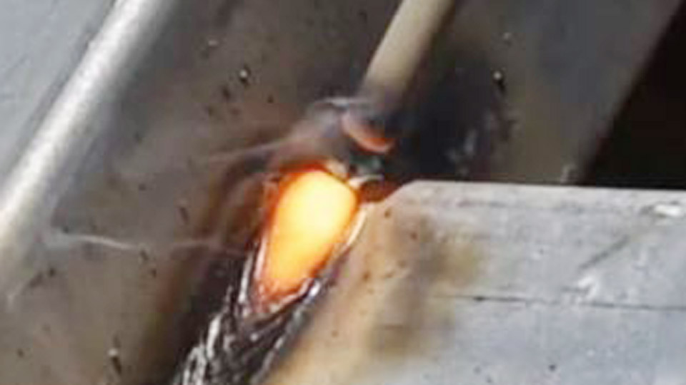
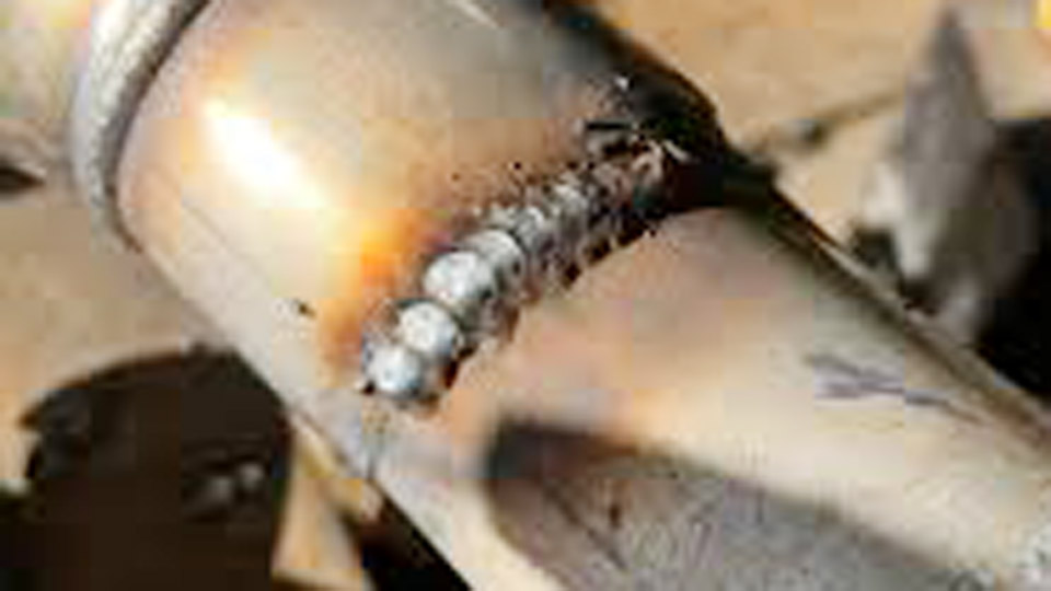
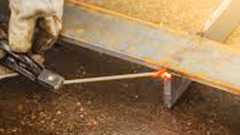
Thin sheet metal is one of the most challenging materials to weld with a stick electrode because it is highly susceptible to burn-through, warping, and poor arc control. Understanding how to weld thin sheet metal with a stick welder is essential when a MIG or TIG machine is unavailable or when field repairs require the portability of SMAW.
Success depends on selecting the right electrode, using low amperage, maintaining a short arc length, and controlling heat input to achieve adequate penetration without damaging the base metal. Even small mistakes in settings or technique can lead to excessive distortion, weak welds, or costly rework.
With the correct approach, however, stick welding can produce reliable results on thinner materials than many welders expect. I’ll explain the practical principles needed to improve weld quality, reduce common defects, and make consistent welds on thin sheet metal with confidence.
Image by red-d-arc
Electrode Selection for Thin Sheet Metal
Why Smaller Diameters Dominate
Smaller electrodes limit molten pool size and heat input. A 1/16-inch or 3/32-inch rod deposits less filler metal per pass than a 1/8-inch rod, reducing the risk of melting through the base material. Larger rods require higher amperage, which compounds heat buildup in thin stock.
Recommended Electrodes and Their Performance
E6013: The top choice for clean mild steel sheet metal. It produces a soft, stable arc with shallow penetration, easy slag removal, and low spatter. Runs well on AC or DC.
E7014: Offers slightly higher deposition with a smooth bead and good all-position performance. Useful when a bit more strength is needed without aggressive digging.
E6011: Suitable for lightly rusty or painted surfaces due to its digging arc. Use cautiously on thin metal as it penetrates deeper; reserve for situations where cleaning is impractical.
Comparison Table:
| Electrode | Diameter | Best For | Key Characteristics | Polarity Options |
|---|---|---|---|---|
| E6013 | 1/16″–3/32″ | Clean sheet metal | Soft arc, minimal penetration, easy slag | AC / DCEN / DCEP |
| E7014 | 3/32″ | Light fabrication | Smooth bead, moderate deposition | AC / DCEN |
| E6011 | 3/32″ | Rusty or dirty surfaces | Digging arc, fast-freeze slag | AC / DCEP |
Avoid E7018 on thin material—it runs hotter and is designed for thicker structural work. Always store rods in a dry environment to prevent moisture-related issues.
Machine Settings and Polarity Decisions
Amperage Guidelines by Thickness and Rod Size
Start at the low end of the recommended range and test on scrap identical to your workpiece. Thin metal demands conservative settings to form a puddle without excessive spread.
Typical Starting Amperage Ranges (DC preferred):
| Metal Thickness (Gauge / Inches) | Rod Diameter | Amperage Range (DC) | Notes |
|---|---|---|---|
| 22–24 ga (0.025–0.030″) | 1/16″ | 20–45 A | Ultra-light; whip technique |
| 20–18 ga (0.036–0.048″) | 1/16″–3/32″ | 40–65 A | Most common sheet metal range |
| 16 ga (0.060″) | 3/32″ | 50–80 A | Allow slight weave if needed |
Polarity Impact on Heat Input
DCEN (Electrode Negative): Preferred for thin sheet. Directs more heat to the electrode, resulting in shallower penetration and lower base metal heating—ideal for preventing burn-through.
DCEP (Electrode Positive): Increases penetration and heat in the workpiece. Use only when deeper fusion is required and monitor closely.
AC: Viable with E6013; arc is less stable than DC but workable on many machines. Expect slightly more spatter.
Dial arc force low on inverter machines for better control at low amperage. Use hot start sparingly to avoid initial burn-through. Always verify settings on scrap first—machine calibration varies.
Joint Preparation and Setup Techniques
Cleaning and Fit-Up
Remove rust, paint, oil, and mill scale from the weld zone and adjacent areas using a grinder, wire brush, or chemical degreaser. Contaminants destabilize the arc and introduce porosity. Ensure tight fit-up with minimal gaps—clamp or tack pieces securely to prevent movement as heat builds.
Backing and Heat Sinks
Clamp a copper or aluminum backing bar behind the joint. These materials absorb excess heat effectively without fusing to the workpiece. For field repairs without backing, use scrap steel or ceramic tiles as temporary supports. This setup is particularly valuable on butt joints or patches.
Tack Welding Strategy
Place small tacks (1/4-inch or less) every 1–3 inches along the joint, alternating sides. Allow cooling between tacks. This locks alignment and distributes initial heat without warping the panel. Skip welding (intermittent beads) builds on this foundation.
Core Welding Techniques for Control
Arc Length and Electrode Angle
Maintain a short arc length—approximately equal to the electrode diameter (e.g., 1/16 inch for a 1/16-inch rod). Longer arcs increase voltage, heat, and spatter. Hold the electrode at a 10–15° drag angle (leaning slightly away from travel direction) for better puddle control and visibility.
Travel Speed and Stitch/Whip Method
Move faster than on thicker plate. Use stitch welding: deposit short beads (1/2–1 inch), pause to let the puddle cool and solidify, then advance. The whip technique—strike, pause briefly to build puddle, whip forward slightly, and repeat—further limits heat input. Aim for a narrow bead width, roughly 2–3 times the rod diameter.
Position-Specific Adjustments
- Flat/Horizontal: Easiest. Consistent drag works well.
- Vertical: Weld downhill with E6013 for faster travel and less heat soak. Uphill increases heat input—avoid on very thin material.
- Overhead: Reduce amperage further and use very short stitches to combat gravity on the puddle.
Practice on scrap in the target position to refine rhythm before the final piece.
Common Challenges and Targeted Solutions
Burn-Through Prevention
Primary causes include high amperage, slow travel, or long arcs. Solutions: smallest viable rod, DCEN polarity, backing, and stitch welding. If a hole forms, grind it clean and patch with a larger overlapping piece using the same low-heat approach.
Warping and Distortion
Thin metal expands and contracts rapidly. Counter this with balanced tacking, skip welding patterns (weld, skip, return), and clamping to a heat sink or rigid fixture. Allow full cooling between major segments.
Porosity, Lack of Fusion, and Spatter
- Porosity: Improve cleaning and maintain short arc.
- Lack of fusion: Slight increase in amperage or better angle if puddle doesn’t tie in.
- Spatter: Short arc and correct polarity reduce it significantly.
Post-weld: Chip slag thoroughly and inspect for uniform bead profile without undercut or excessive convexity.
Advanced Considerations for Real-World Applications
Material Variations
Mild steel responds best to the techniques above. For galvanized sheet, grind off the coating in the weld zone to avoid toxic fumes and porosity—use ventilation and consider E6011 for better tolerance of residues.
Stainless thin sheet requires even lower heat and specialized rods if corrosion resistance is critical, though stick is rarely first choice here.
Multi-Pass Strategy
On edges or slightly thicker transitions (e.g., 16 ga to 14 ga), use stringer beads with interpass cooling. Avoid weaving on thin sections as it concentrates heat.
Machine and Accessory Choices
Inverter welders with good low-amperage performance outperform older transformers for this work. Adjustable arc force and hot start features aid consistency. A good auto-darkening helmet (shade 9–11) and proper ground clamp placement (close to the joint) improve visibility and arc stability.
When to Switch Processes
Stick excels in outdoor or no-gas scenarios but yields to MIG (short-circuit mode with 0.023–0.030″ wire) or TIG for production thin sheet work requiring minimal cleanup and distortion. Understand these trade-offs for project planning.
Decision-Making Summary and Pro Insight
Mastering thin sheet metal with a stick welder comes down to deliberate heat management: select E6013 or similar small-diameter rods, set conservative amperage on DCEN, prioritize short arcs and stitch techniques, and prepare joints meticulously with backing where possible.
Test relentlessly on scrap matching your material and conditions. These choices determine whether you achieve strong, clean welds or repeated frustration.
At a pro level, the real differentiator is treating every thin weld as a heat-balancing exercise—view the puddle as a dynamic system you control through rhythm rather than force. This mindset extends directly to more complex fabrication where precision heat input defines structural integrity and appearance.
FAQ
What is the best electrode for welding thin sheet metal with a stick welder?
E6013 in 1/16″ or 3/32″ diameter. It delivers a smooth arc, shallow penetration, and easy control, minimizing burn-through on clean mild steel.
What amperage should I use for 18-gauge sheet metal?
Start at 40–60A with a 1/16″–3/32″ rod on DCEN. Test on scrap and adjust up in small increments only if fusion is insufficient.
Can you stick weld galvanized thin sheet metal?
Yes, but grind or remove the zinc coating thoroughly in the weld area first to prevent porosity and fumes. Use E6011 if residues remain, maintain excellent ventilation, and follow low-heat practices.
How do you prevent warping when stick welding thin metal?
Use frequent small tacks, stitch welding with cooling pauses, tight clamping to a heat sink, and balanced welding sequences that alternate sides of the joint.